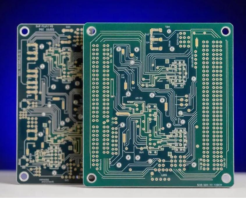
When a 2-layer PCB fails EMC pre-compliance: the 4-layer engineering decision
Scenario: A WiFi-enabled IoT sensor board (ESP32 + temperature sensor + relay driver) designed on standard 1.6 mm 2-layer FR-4. The prototype function-tested fine. At the EMC pre-scan, radiated emissions failed at 240 MHz (the WiFi 2.4 GHz second harmonic from digital noise coupling onto the antenna trace). The 2-layer board lacked a continuous ground reference plane beneath the RF section. The fix was not a better layout on 2 layers — it was a structural change to 4 layers with an internal ground plane directly beneath the top signal layer, reducing the loop area by approximately 80%.
This is the most common entry point into 4-layer PCB design: a product that works electrically but fails reliably on a 2-layer board because signal integrity, EMI, or power distribution reach their practical ceiling. The 4-layer PCB solves these problems by adding internal copper planes that serve as low-impedance return paths, electromagnetic shields, and distributed power delivery — but only when the stackup, material, and impedance targets are engineered correctly from the start.
This page is structured as a consultation document, not a product catalogue. It covers the three common 4-layer stackup architectures, the impedance control methodology XFPCB uses to hit 50 Ω, 90 Ω differential, and 100 Ω differential targets, material selection with real TG and DK values, thermal management design, and the DFM rules that separate a reliable 4-layer board from one that warps, fails isolation testing, or delivers impedance outside tolerance.
Three 4-layer stackup architectures: which one fits your design?
There is no single "standard" 4-layer stackup. The optimal architecture depends on signal type, impedance targets, board thickness, and cost constraints. Below are three proven architectures XFPCB manufactures. Each is shown with typical dielectric thicknesses, copper weights, and impedance outcomes.
Dual ground: Signal – GND – GND – Signal
Best isolation • Sensitive analogueImpedance-optimised: Signal – GND – Signal – Signal
Impedance-critical • RF • PremiumQuick decision guide
- Choose Architecture A when: your design is primarily digital (≤1 GHz), cost matters, and you need a reliable GND plane with split VCC on L3.
- Choose Architecture B when: you have sensitive analogue circuitry sharing a board with digital noise sources, or you need maximum EMI suppression in a thin form factor.
- Choose Architecture C when: impedance tolerance matters more than cost, you need predictable 50 Ω, 90 Ω diff, or 100 Ω diff, or you are using Rogers material for RF performance.
Controlled impedance on 4-layer PCBs: target selection, stackup tuning, and manufacturing tolerance
A 4-layer board's primary advantage over 2-layer for impedance control is the ability to define the dielectric distance between the signal layer and its reference plane independently of the total board thickness. The prepreg between L1 and L2 (or L4 and L3) is a design variable — not a fixed core thickness. This section documents the methodology XFPCB uses to calculate and verify impedance for 50 Ω single-ended, 90 Ω differential, and 100 Ω differential targets.
Select target impedance and tolerance
Common targets: 50 Ω single-ended (RF, WiFi, Bluetooth, general high-speed), 90 Ω differential (USB 2.0/3.0, LVDS), 100 Ω differential (Ethernet, HDMI, DisplayPort). Standard tolerance: ±10%. Tight tolerance (±8% or ±5%) available with impedance coupon testing and pre-production verification.
Determine material dielectric constant (Dk) at operating frequency
FR-4 Dk varies with frequency: ~4.5 at 1 MHz, ~4.2 at 1 GHz, ~4.0 at 3 GHz. XFPCB uses frequency-dependent Dk values for impedance calculations — not the 1 MHz datasheet value. For Rogers RO4003C: Dk = 3.38 at 10 GHz (stable). For RO4350B: Dk = 3.48 at 10 GHz. Using the wrong Dk value produces trace widths that are systematically off by 10–15%.
Calculate trace geometry from target Z0 and dielectric height
For a microstrip trace on L1 over L2 GND plane, the characteristic impedance is approximately:
Where h = dielectric height (prepreg thickness), w = trace width, t = copper thickness. XFPCB uses field solvers (Polar Si9000 or equivalent) for exact calculations, but this formula gives the first-pass estimate. For a 1.6 mm board with 0.20 mm prepreg (Architecture A), 50 Ω requires a trace width of approximately 0.30–0.35 mm with 1 oz copper.
Differential pair design (90 Ω and 100 Ω)
For edge-coupled differential microstrip on L1 over L2 GND:
- Trace width: 0.15–0.22 mm
- Pair gap: 0.15–0.25 mm
- Prepreg h: 0.10–0.20 mm
- Copper: 0.5 oz (18 µm) recommended
- Trace width: 0.12–0.18 mm
- Pair gap: 0.20–0.30 mm
- Prepreg h: 0.10–0.20 mm
- Copper: 0.5 oz (18 µm) recommended
Thinner copper (0.5 oz) produces finer traces and tighter impedance control because the etch factor has less influence on the cross-section. XFPCB can plate up to the required final copper thickness after etching.
Verification: impedance coupons and TDR testing
XFPCB places impedance coupons on each production panel (typically one per panel edge, matching the layer stackup). After fabrication, the coupons are measured with a TDR (Time Domain Reflectometer) to verify actual impedance against target. Results are recorded and delivered with the shipment. For tight-tolerance orders (±8% or better), we recommend pre-production test panels to validate the stackup before committing to the full production run.
Impedance target reference (Architecture A, 0.5 oz Cu, FR-4)
| Target | Prepreg h (mm) | Trace width (mm) | Pair gap (mm) | Tolerance |
|---|---|---|---|---|
| 50 Ω SE | 0.20 | 0.32 | — | ±10% |
| 50 Ω SE | 0.15 | 0.26 | — | ±10% |
| 90 Ω diff | 0.15 | 0.18 | 0.20 | ±10% |
| 100 Ω diff | 0.15 | 0.15 | 0.25 | ±10% |
| 100 Ω diff | 0.20 | 0.18 | 0.30 | ±10% |
Values shown are first-pass estimates for FR-4 (Dk = 4.2 at 1 GHz). Final dimensions are computed by XFPCB's CAM engineers using Polar Si9000 against your specific stackup and material. Send your target impedance with the RFQ so the dielectric stack can be verified before layout is frozen.
Laminate selection for 4-layer PCBs: TG135, TG170, and RF-grade materials
The material system for a 4-layer board includes the core laminate (between L2 and L3), the prepreg bonding sheets (between L1–L2 and L3–L4), and the copper foil. Each material choice affects impedance stability, thermal reliability, dimensional registration, and cost. The table below shows the three material classes XFPCB recommends for 4-layer boards.
TG135 FR-4
Cost index: 1.0× (baseline) Standard • General purposeTG170 FR-4 (High-Tg)
Cost index: 1.15–1.25× Recommended • Multilayer defaultRogers (RO4003C / RO4350B)
Cost index: 4–8× RF-grade • PremiumMaterial selection cheat sheet
Thermal management on 4-layer PCBs: what the internal planes actually do
One of the less-discussed advantages of 4-layer boards is thermal performance. The internal copper planes act as heat spreaders — but their effectiveness depends on copper weight, plane continuity, via stitching, and the thermal conductivity of the dielectric between layers. This section provides specific numbers and design rules.
Copper plane thermal spreading
A solid copper plane (1 oz, 35 µm) has a thermal conductivity of ~385 W/m·K in-plane, compared to the through-plane conductivity of FR-4 (~0.3 W/m·K) — a ratio of more than 1,000:1. A 1 oz copper plane can spread heat laterally at roughly the same efficiency as a 0.35 mm aluminium plate. For a 100×80 mm 4-layer board with solid GND and power planes on L2 and L3, the effective heat spreading area is approximately 160 cm² (both planes combined).
Thermal via arrays: when one plane is not enough
For components dissipating >0.5 W (voltage regulators, power MOSFETs, RF PAs), the thermal resistance from the component pad to the internal plane must be minimised. Thermal via arrays — typically 9–16 vias under the component pad — provide a low-thermal-impedance path from L1 to L2 (GND plane). The effective thermal resistance of a via array depends on via count, via diameter, and copper plating thickness.
Via arrays are most effective when (a) the vias are filled or tented to prevent solder wicking, (b) the via barrel plating is at least 25 µm, and (c) the vias directly connect to the GND plane without thermal spokes. For high-power components, XFPCB recommends filled vias with cap plating.
Copper weight selection for thermal performance
On a 4-layer board, the internal copper weight affects heat spreading more than the outer layers because the internal planes have continuous copper area (no component pads breaking the plane). XFPCB's recommended copper weight configurations for thermal management:
| Configuration | Heat spreading | Min trace/space | Cost impact | Best for |
|---|---|---|---|---|
| 1 oz all layers | Standard | 0.10/0.10 mm | Baseline | Most 4-layer designs |
| 1 oz outer, 2 oz inner | Good (inner planes spread heat 2× better) | 0.15/0.15 mm (inner) | +10–20% | Power electronics with moderate dissipation |
| 2 oz all layers | High | 0.20/0.20 mm | +25–40% | High-current motor drives, LED arrays |
Increasing inner plane copper from 1 oz to 2 oz doubles the cross-sectional area for heat conduction. For a board with 10 W total dissipation, this typically reduces the hot-spot temperature by 5–10°C depending on board size and airflow.
Board thickness and thermal impedance
The thermal resistance from L1 (component side) to L2 (GND plane) is proportional to the prepreg thickness. Thinner prepreg = lower thermal resistance:
For power components, use vias to bypass the prepreg layer. The through-plane thermal resistance of a single 0.3 mm via is approximately 0.5°C/W per via (substantially lower than through the prepreg alone).
The 4-layer DFM code: rules XFPCB checks during CAM review
These are not generic PCB guidelines. Each rule addresses a failure mode that appears specifically on 4-layer boards — where inner planes, registration between layers, and lamination physics create constraints that do not exist on simpler stackups.
Copper balance across all four layers must be within 20 points
During lamination, uneven copper distribution creates differential resin flow and uneven pressure across the panel. If L1 has 80% copper and L2 has 20%, the prepreg between them will experience uneven resin squeeze-out, leading to local thickness variations, impedance shifts, and board warp. XFPCB's CAM team flags any layer pair where copper percentage differs by more than 20 percentage points.
Drill-to-copper clearance on inner layers ≥ 0.30 mm (12 mil)
Non-plated holes (mounting holes, tooling holes, edge slots) must maintain at least 0.30 mm clearance from any inner-layer copper feature. At 0.30 mm, the drill wander tolerance of ±0.08 mm is safely absorbed. Below 0.25 mm, drill breakout into the inner plane can expose copper inside the hole wall, creating a short or corrosion path. For plated through-holes that must connect to an inner plane, the clearance is defined by the annular ring on that layer (minimum 0.15 mm annular ring for inner layers).
Plane openings (anti-pads) must be at least 0.20 mm larger than the drill diameter
When a PTH via passes through an inner plane layer without connecting to it, the anti-pad (clearance hole in the copper) must be large enough to prevent inadvertent connection from drill wander, image registration error, or plating flash. The minimum anti-pad diameter is drill diameter + 0.40 mm (i.e., 0.20 mm clearance on each side). For high-voltage planes (>50 V), increase to drill diameter + 0.60 mm.
Resin flow zones: minimum copper-free area on inner layers ≥ 10×10 mm
Large copper-free voids on inner layers can fill incompletely during lamination if surrounding copper areas restrict resin flow. Resin-starved areas create dielectric voids, which can cause impedance variation, CAF (conductive anodic filament) growth, and mechanical weakness. XFPCB's rule: any copper-free area larger than 10 mm in either dimension must be checked for resin fill adequacy. For large open areas (>50 mm), add flow-enhancing channels or dot patterns in the copper plane.
Buried/blind vias are not recommended on a 4-layer board
A 4-layer stackup with only through-hole vias is the most reliable and cost-effective configuration. Buried vias (connecting L2 to L3) and blind vias (connecting L1 to L2) are technically possible but require sequential lamination cycles, increasing cost by 40–60% and introducing additional reliability risks (dielectric fill voids, plating shadowing). In almost every 4-layer design, all necessary routing connections can be made with through-hole vias, sometimes combined with microvias if HDI features are required. If blind/buried vias appear necessary, consider whether a 6-layer board would be more cost-effective.
Layer registration tolerance: include ±0.10 mm for inner-layer feature placement
During lamination, the four copper layers are aligned using optical registration targets. The typical registration tolerance between layers is ±0.10 mm (4 mil). This means an inner plane pad that should be centred on a PTH via may be offset by up to 0.10 mm. Ensure annular ring dimensions on inner layers account for this offset on top of the drill registration tolerance. For reliable fabrication, inner-layer annular ring should be ≥0.15 mm after accounting for both registration and drill tolerances.
XFPCB performs all six checks (and approximately 30 more) during CAM review for every 4-layer order. Our DFM report is delivered before fabrication and includes flagged items, recommendations, and required-approval items. No production starts without your sign-off on the DFM findings.
Submit your design for DFM reviewWhat drives the cost of a 4-layer PCB: a supply-side breakdown
Unlike 2-layer boards where material is the dominant cost factor, a 4-layer PCB's cost is distributed across laminate materials, prepreg, lamination cycles, drilling time, plating, and inspection. Understanding this breakdown helps procurement teams target their cost-reduction efforts where they have the most leverage.
Laminates and prepreg
30% of board costCore laminate (L2–L3 substrate) and two prepreg bonding sheets (L1–L2 and L3–L4). Cost varies directly with material grade: TG170 adds ~15–20% over TG135; Rogers adds 300–700% for the affected layers. The core is the largest single laminate piece; substituting it from TG135 to TG170 has the most impact on total material cost.
Lamination
15% of board costEach lamination cycle takes 60–90 minutes at 180–200°C under pressure, plus cool-down. A 4-layer board requires one lamination cycle (inner layers + prepreg + outer foil stacked and pressed). By comparison, a 2-layer board has no lamination step (core is pre-bonded). The lamination press's capacity is the bottleneck in most PCB factories — complex stackups with multiple material types require dedicated press setups.
Drilling
18% of board costDrilling a 4-layer board takes approximately 2× longer than a 2-layer board of the same hole count because the stack height is similar but the four-layer target registration requires slower feed rates. Tool wear is also higher: drilling through copper on all four layers accelerates bit wear. A 0.3 mm drill bit typically lasts 3,000–5,000 hits on 4-layer vs 8,000–12,000 on 2-layer. The drilling step is also where minimum hole size directly affects cost: 0.25 mm bits cost ~30% more and wear faster than 0.3 mm.
Plating and surface finish
12% of board costElectroless copper plating deposits copper (~25 µm) on all hole walls and exposed surfaces. On a 4-layer board, the PTH barrel must plate uniformly through ~1.6 mm of laminate — aspect ratio of 5:1 for 0.3 mm holes, which is well within standard plating capability but requires longer plating time than 2-layer boards. Surface finish adds cost on top of the base copper: ENIG adds ~50 100% vs lead-free HASL, but the absolute cost difference is material cost × board area, so it is proportionally less of the total on a 4-layer board than on a 1-layer board.
Cost summary: 4-layer vs alternatives (100×80 mm board, 100 pcs, standard spec)
| Board type | Typical unit price range | Cost index | Key cost driver |
|---|---|---|---|
| 1-layer (CEM-1, HASL) | $0.30–0.70 | 0.3–0.5× | Material + punching tooling |
| 2-layer (FR-4, HASL) | $0.80–1.20 | 1.0× (baseline) | Material + drilling |
| 4-layer (FR-4 TG170, HASL) | $1.40–2.20 | 1.5–1.8× | Laminate + lamination + drilling |
| 4-layer (FR-4 TG170, ENIG) | $1.80–3.00 | 1.9–2.5× | Laminate + finish |
| 4-layer (Rogers hybrid, ENIG) | $4.00–12.00 | 4–10× | Rogers laminate cost |
Prices are for reference based on XFPCB standard production. Actual pricing depends on board dimensions, quantity, surface finish, impedance testing requirements, lead time, and delivery destination. Request a custom quotation for your specific design.
Where 4-layer PCBs solve real engineering problems
Each application below represents an RFQ category XFPCB fulfils regularly. The common engineering thread: 2-layer was insufficient (EMI, routing density, or impedance), and 6-layer was unnecessary.
WiFi / BLE / Zigbee modules
Wireless modules require continuous ground beneath the antenna feed trace, tightly controlled 50 Ω impedance to the antenna connector, and minimal digital noise coupling from the host MCU. A 4-layer board (Architecture A or C) provides the GND reference plane and impedance-controlled interface that a 2-layer board cannot deliver reliably.
Ethernet switch and PoE interfaces
100 Ω differential pairs for Ethernet PHY-to-RJ45 traces require consistent impedance across the entire route. 4-layer provides the reference plane under both traces of each pair. Split planes on L3 isolate the PoE power feed from the signal return path.
USB 2.0 / USB 3.0 hub and interface boards
USB 2.0 requires 90 Ω differential impedance; USB 3.0 adds 100 Ω diff for the SuperSpeed pair. A 4-layer board with 0.5 oz outer copper (Architecture C) allows fine enough traces for the required differential geometry while maintaining the reference plane on L2.
Industrial sensor fusion boards
Combining analogue sensor front-ends (thermocouple, strain gauge, 4–20 mA) with digital control logic (CAN bus, RS-485) on one board requires clean power and ground isolation. Architecture B (dual ground planes) provides the separation needed to keep digital return currents out of the analogue reference — a common problem on 2-layer boards.
Motor drive controller boards
BLDC motor drivers combine high-current power traces (2–10 A) with low-voltage logic and sensor feedback. Thicker inner copper (2 oz on L2/L3) spreads MOSFET and driver heat while the outer layers handle high-current routing and logic. 4-layer avoids the copper-space compromises that force wide trace detours on 2-layer boards.
Audio DAC and preamplifier boards
High-end audio DACs (AKM, ESS, Cirrus Logic) require separate analogue and digital ground returns, low-noise power supplies, and minimal crosstalk between channels. Architecture B with solid ground planes on L2 and L3 provides the isolation that separates digital noise (from the I2S or USB interface) from the analogue audio path without adding PCB size.
Send your 4-layer PCB project for stackup review and quotation
XFPCB treats every 4-layer PCB RFQ as an engineering consultation. We review the stackup, impedance requirements, material selection, and DFM considerations before providing a quotation — not after. The typical response includes a recommended stackup architecture, suggested material, impedance feasibility assessment, and DFM findings.
To include for a complete engineering review:
- Gerber files (RS-274X) with all copper, soldermask, silkscreen, and outline layers
- NC drill file with tool list and drill symbol definitions
- Stackup diagram or specification (target board thickness, layer purpose, dielectric type)
- Impedance targets if applicable: 50 Ω SE, 90 Ω diff, 100 Ω diff — which layer and which signals
- Material preference: TG135, TG170, or Rogers — or let XFPCB recommend based on your design
- Quantity (prototype + production tier if known)
- Delivery country and preferred shipping method