
Industry-Leading
Multilayer PCB Manufacturer (4 to 40 Layers)
The Ultimate Guide to Stackups, Processes, and Engineering
Welcome to the core pillar of modern electronics. Whether you are an IoT designer developing a compact 4-layer sensor, or an industrial engineer architecting a 24-layer high-speed backplane, understanding how a multilayer printed circuit board is manufactured is crucial to your success. As a globally recognized multilayer PCB manufacturer, XingFeng PCB has created this comprehensive guide to help you navigate layer counts, understand the physics of stackups, identify key cost drivers, and ultimately choose the perfect fabrication strategy for your next hardware innovation.
Discuss Your Multilayer Project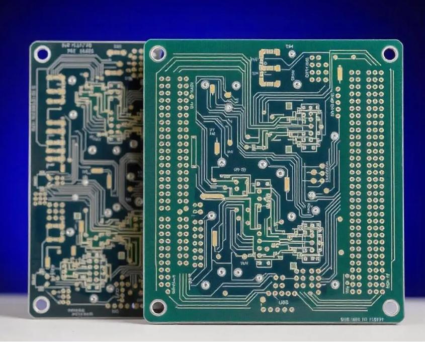
What is a Multilayer PCB?
A multilayer PCB is defined as any printed circuit board containing three or more conductive copper layers. In practice, they are almost exclusively manufactured in even numbers (4, 6, 8, 10, etc.) to maintain mechanical symmetry and prevent severe warpage during the heating and cooling cycles of manufacturing.
The Three Fundamental Building Blocks
To understand a multilayer board, you must understand its three raw ingredients, which are stacked like a highly complex sandwich:
- The Core: This is a rigid piece of fiberglass-epoxy (typically FR-4) that has solid copper foil pre-bonded to both sides. It is fully cured and acts as the structural foundation of the inner layers.
- Prepreg (Pre-impregnated): This is fiberglass cloth that has been saturated with epoxy resin but is only partially cured (B-stage). During the lamination press cycle, it acts as the "glue." It melts, flows around the etched copper traces of the cores, and then fully cures (C-stage) to bind the entire board together.
- Copper Foil: Thin sheets of raw copper that are pressed onto the outermost layers (Top and Bottom) of the stackup.
The Multilayer Manufacturing Process
Fabricating a multilayer PCB is vastly more complex than producing a simple double-sided board. The inner layers must be completely finished and inspected before the board is even pressed together. Here is the step-by-step journey:
1. Inner Layer Imaging & Etching
The raw copper cores are coated with photoresist. Laser Direct Imaging (LDI) exposes the circuitry pattern. The unexposed copper is chemically etched away, leaving only the desired inner traces and ground planes.
2. Automated Optical Inspection (AOI)
Because inner layers cannot be fixed after lamination, every etched core is optically scanned against the original Gerber data to ensure there are absolutely no microscopic shorts or broken traces.
3. Brown Oxide Treatment
The smooth etched copper on the inner layers is chemically treated to create a microscopic, rough, crystalline surface (Brown Oxide). This is critical; it gives the melting prepreg resin something to physically grip onto during lamination.
4. Lamination (The Press)
The cores, prepreg, and outer copper foils are stacked in a highly precise "book." They are placed into a vacuum hydraulic press where extreme heat (200 - C+) and pressure fuse them into a single, solid block.
5. Drilling & Plating
Mechanical drills bore through the solid multilayer block. An electroless copper deposition process coats the fiberglass walls of the holes, followed by electroplating, creating the electrical connection between the layers.
How to Choose Your Layer Count
Choosing the correct layer count is a balancing act between routing density, signal integrity, and cost. Here is a general guideline to help hardware architects navigate the decision:
- 4-Layer PCBs: The baseline for modern electronics. Used for simple IoT devices, basic motor controllers, and smart home gadgets. It provides dedicated internal VCC and GND planes, which drastically reduces EMI compared to a 2-layer board.
- 6-Layer PCBs & 8-Layer PCBs: The standard for industrial controls, automotive dashboards, and advanced motherboards. These layer counts allow for strict impedance control (for USB, HDMI, PCIe) and multiple power domains.
- 10-Layer to 16-Layer PCBs: Required for enterprise network switches, aerospace avionics, and high-density BGA fan-outs. This is where High-Density Interconnect (HDI) and blind/buried vias become common to save routing space.
- 20-Layer to 40-Layer PCBs: The absolute extreme. Used exclusively for ATE Load Boards, supercomputer backplanes, and terabit core routers. Characterized by thick boards, heavy copper, and ultra-low loss materials (Megtron 6).
Standard vs. Advanced Stackups
To illustrate the difference in engineering, let us compare a standard 6-layer stackup with an advanced 10-layer HDI stackup.
| Standard 6-Layer Stackup (Through-Hole) | Advanced 10-Layer HDI Stackup (1+8+1) |
|---|---|
| L1: Top Signal / Components | L1: Top Signal (Microvias down to L2) |
| Prepreg | Prepreg (Laser drillable) |
| L2: Solid Ground Plane (GND) | L2: Solid Ground Plane (GND) |
| Core | Core (Buried Vias L2 to L9) |
| L3: Inner Signal 1 | L3 & L4: Inner High-Speed Signals |
| Prepreg | Prepreg / Core Structure |
| L4: Inner Signal 2 | L5 & L6: Multiple Power Planes (VCC) |
| Core | Prepreg / Core Structure |
| L5: Power Plane (VCC) | L7 & L8: Inner High-Speed Signals |
| Prepreg | Core |
| L6: Bottom Signal | L9: Solid Ground Plane (GND) |
| Vias: All vias go entirely through L1 to L6. | L10: Bottom Signal (Microvias up to L9) |
Cost Drivers in Multilayer PCBs
As a procurement director or engineer, it is vital to understand what drives the price of a multilayer board. The raw material (FR-4) is often the cheapest part of the equation.
- Layer Count: Every additional layer requires more core material, more prepreg, and crucially, more processing time (inner layer imaging, etching, AOI, oxide). A 12-layer board takes significantly longer to manufacture than a 4-layer board.
- Blind and Buried Vias (HDI): Standard through-holes are drilled once after lamination. Blind/Buried vias require the factory to laminate a sub-stack (e.g., layers 2 through 9), drill it, plate it, and then laminate the outer layers on top. This sequential lamination drastically increases cost and manufacturing time.
- Advanced Materials: Standard High-Tg FR-4 (like Isola 370HR) is cost-effective. Ultra-low loss materials for RF and high-speed digital (like Rogers RO4350B or Panasonic Megtron 6) can cost 3x to 5x more than FR-4.
- Tight Tolerances: Requesting 3 mil / 3 mil (0.075mm) trace/space, or 鍗?% impedance control requires the factory to use slower, higher-precision Laser Direct Imaging (LDI) and results in lower overall yield rates, which increases the price per board.
The Ultimate Multilayer PCB FAQ
Answers to the top 10 most common technical and commercial questions we receive from global engineering teams regarding multilayer fabrication.
1. Why are multilayer PCBs always manufactured in even numbers (4, 6, 8 layers)?
It is entirely about mechanical stability. During lamination, the board is subjected to extreme heat. If a board has an odd number of layers (e.g., 5 layers), the copper weight and dielectric thickness are asymmetrical across the Z-axis center. As the board cools, the different layers will contract at different rates, causing the board to permanently warp or bow, rendering it impossible to assemble.
2. What is the maximum thickness for a multilayer board?
Standard PCBs are 1.6mm thick. For multilayer backplanes (20 to 40 layers), we can manufacture boards up to 7.0mm or 8.0mm thick. The primary limitation is the aspect ratio of the drilled holes (the depth of the hole divided by its diameter), which dictates how effectively we can electroplate copper into the barrel.
3. What is the "Aspect Ratio" and why does it matter?
Aspect Ratio = Board Thickness / Drilled Hole Diameter. If you have a 3.2mm thick board and a 0.2mm drill hole, the ratio is 16:1. High aspect ratios (above 12:1) make it extremely difficult for plating chemistry to flow into the center of the hole. We utilize advanced pulse plating to achieve ratios up to 20:1 or higher for complex builds.
4. How do you prevent internal layers from shifting during lamination?
We use sophisticated optical Direct Imaging (DI) systems. We measure the exact stretch and shrink of every inner layer after etching, and mathematically scale the drill files and outer layer imaging to match the physical reality of the pressed board, achieving 鍗? mil registration accuracy.
5. What is Via-in-Pad (VIPPO) and when do I need it?
VIPPO (Via-in-Pad Plated Over) is a process where we drill a microvia directly into a BGA surface pad, fill it with epoxy, and plate it flat with copper. It is absolutely necessary for routing high-density BGAs (pitch < 0.65mm) on multilayer boards where traditional "dog-bone" fan-outs will not physically fit.
6. What is "Copper Balancing" and do I have to do it?
Copper balancing involves adding non-functional copper (thieving or cross-hatching) to empty areas of the inner layers. This ensures that every layer has roughly the same percentage of copper density. Yes, you should do it - r our CAM engineers will do it for you. It prevents the board from warping and ensures uniform thickness during pressing.
7. How do you verify that the inner layers are not shorted out?
Because we cannot see the inner layers after lamination, we perform 100% Automated Optical Inspection (AOI) on every single inner core before they go into the press. After the board is finished, we perform 100% electrical flying probe or grid testing to detect any micro-shorts.
8. Can I mix different materials in a multilayer stackup (Hybrid Stackup)?
Yes. To save costs on high-frequency designs, we frequently perform Hybrid Lamination. We might use expensive Rogers RO4350B for the critical outer RF layers (L1-L2), and standard Isola 370HR FR-4 for the inner digital and power planes.
9. What is Back-Drilling (Controlled Depth Drilling)?
In thick multilayer boards, a plated through-hole leaves a "stub" of unused copper if the signal only travels from L1 to L3. At high frequencies (>10 GHz), this stub acts as an antenna and destroys the signal. We use precision depth-controlled drilling from the bottom of the board to physically remove this unused copper stub.
10. What is the typical lead time for a complex multilayer prototype?
A standard 4 to 8-layer prototype can be turned around in 5 to 7 days. However, a complex 16-layer HDI board requires sequential lamination, VIPPO, and extensive CAM engineering. You should expect a lead time of 12 to 18 working days for high-layer-count, advanced prototypes.