
The fab notes say "FR-4" and nothing else. CAM parks the job. Quoting asks which Tg, which IPC-4101 slash sheet, whether lead-free reflow is in play, and whether the stackup needs low-loss glass on signal layers. Buyers hear "we stock FR-4" and assume the simulation and the shelf part are the same material. They are not.
FR-4 is a flame-retardant class, not a single copper clad laminate (CCL) grade. A Tg 130 C core with Df near 0.02 at 1 GHz and a Tg 180 C filled resin with proven CAF resistance both wear the FR-4 label. When the drawing only says FR-4, the shop pulls what is on the rack--and that rack choice may not match the Dk your impedance model used or the Td your multi-reflow profile needs.
This article is written from the factory and buyer side of that friction: what CCL actually is on the panel, which property dials matter on the shop floor, how frequency and reflow filter the grade, when to step up to metal-core, low-loss, or ceramic, and how to write material callouts so CAM does not invent the answer.
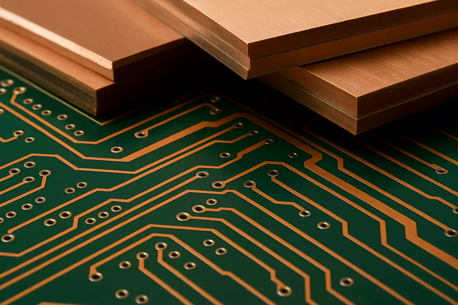
What CCL actually is on the panel
Copper clad laminate is the starting sheet for rigid and flexible PCB fabrication: insulating substrate bonded to copper foil on one or both sides. The copper becomes traces and planes after etch. The dielectric carries mechanical strength, insulation, and the electrical constants that set impedance and loss.
On a typical multilayer build the panel is not one mysterious brick. It is cores (cured CCL with copper), prepreg (B-stage resin/glass that flows in press), and copper foil. Outer foil, inner cores, and bond plies must share a compatible resin family, copper treatment, and CTE story or you invite delamination, registration drift, and via stress.
Classification buyers actually meet on quotes:
| Cut | What shops mean | Buyer note |
|---|---|---|
| Base | Paper (XPC), glass cloth (FR-4 family), composite (CEM-1/CEM-3), metal-base, ceramic-base | Glass-epoxy dominates multilayer; paper/CEM are cost plays for simple 1-2 layer work |
| Resin | Phenolic, epoxy, polyester/polyimide (flex), PTFE/hydrocarbon (RF) | Epoxy FR-4 is the default rigid path; flex and RF change process windows |
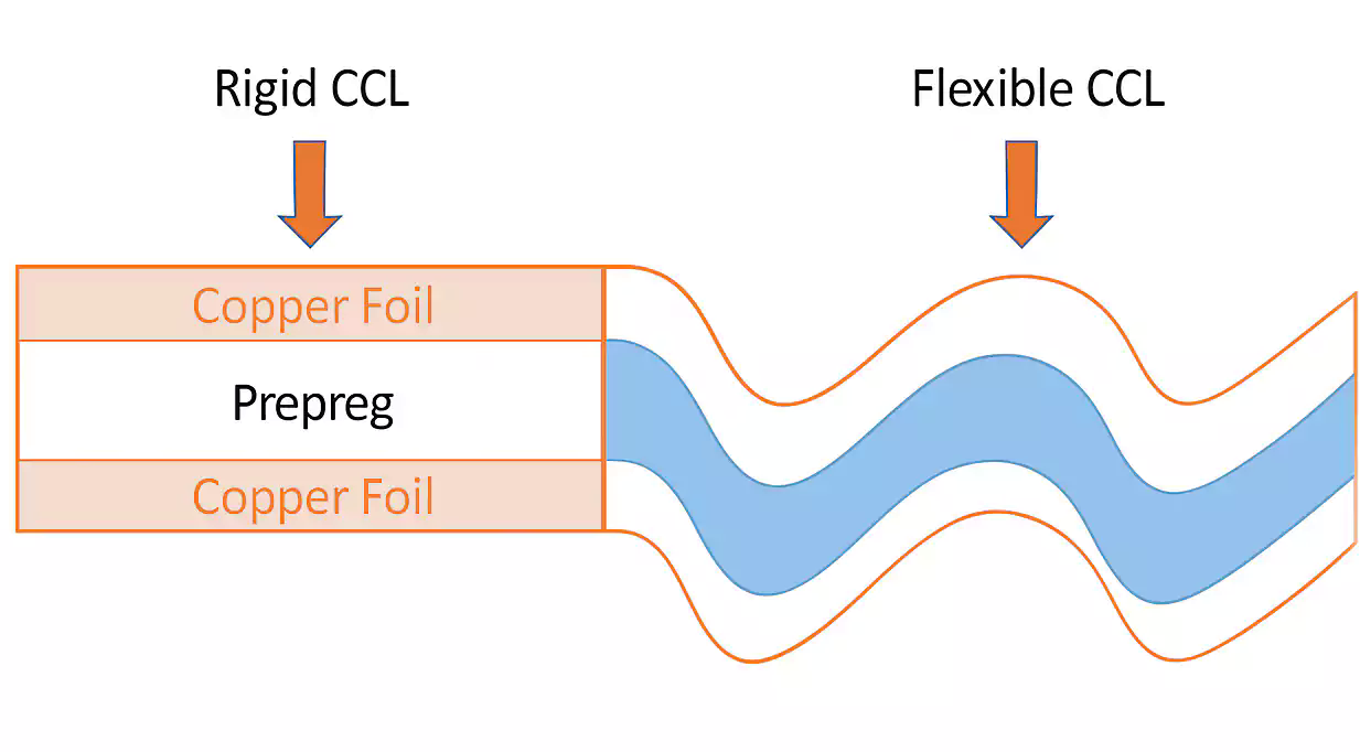
| Rigidity | Rigid CCL vs flexible CCL (FCCL) | Rigid-flex mixes both; call out each region |
| Performance | General-purpose, high heat resistance, low Dk/Df, low CTE | Performance is a dial set, not a marketing adjective |
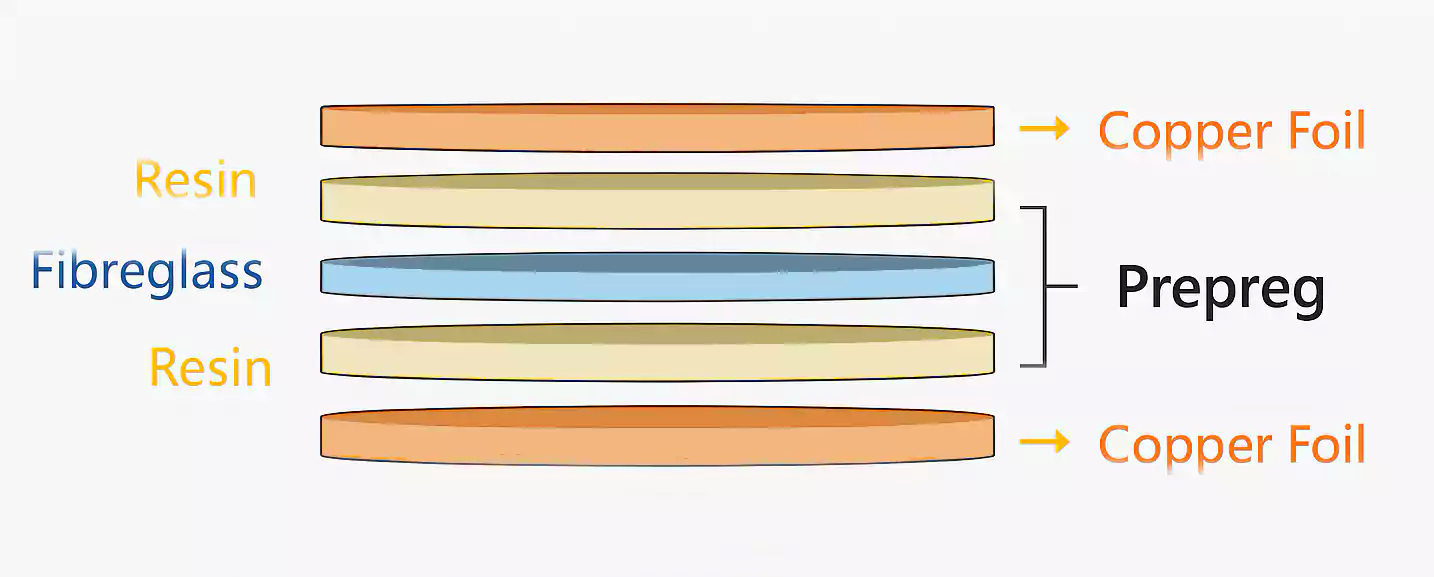
Rigid vs flexible construction changes more than bend radius. Rigid glass-epoxy drills, presses, and etches on standard lines worldwide. Flexible polyimide CCL needs different coverlay, adhesiveless options, and handling. If the RFQ mixes both without a stack sketch, expect a CAM hold.
Property dials buyers should read (shop meaning)
Datasheets list many numbers. The ones that change fab risk, lead time, and field returns are few. Read them as shop constraints, not brochure trivia.
Dielectric constant (Dk) -- Sets propagation delay and controlled-impedance geometry. Standard FR-4 often sits roughly 4.2-4.8 depending on frequency and construction; RF grades go lower. Dk shifts with frequency and moisture. If you lock trace width from a 1 MHz Dk but operate at GHz, expect impedance drift and CAM "width change" proposals.
Dissipation factor (Df) -- Dielectric loss. Everyday FR-4 is often near ~0.02; mid-loss and low-loss families step down toward 0.01, 0.005, and below. Above a few GHz on meaningful route length, Df becomes the reason eye diagrams die even when the stackup drawing looks neat.
Glass transition temperature (Tg) -- Resin softens above Tg; Z-axis CTE jumps. Lead-free SAC reflow peaks near 240-260 C. For lead-free multilayer work, treat Tg >=170 C as a practical floor; Tg ~180 C is safer when the board sees multiple presses and reflows. Specifying "FR-4" without Tg is how low-Tg cores show up on a lead-free traveler.
Decomposition temperature (Td) and T260/T288 -- Td is irreversible resin breakdown; T260/T288 measure time-to-delamination at peak temperatures. Thick, high-layer panels care more about Td and T260 margin than a single Tg number on a marketing slide. Multiple reflow + repair cycles need assembly margin, not just "high Tg" wording.
Z-axis CTE -- Drives via barrel fatigue. HDI, dense BGA, and automotive thermal cycling punish high Z-CTE. Filled high-Tg systems exist specifically to tame expansion through the stack.
Peel strength -- Copper-to-dielectric adhesion. Heavy copper, fine features after thermal stress, and aggressive rework expose weak peel. Ask for values that match copper weight and process, not a generic "meets FR-4."
Moisture absorption -- Water raises effective Dk/Df and feeds CAF risk. Humid logistics and bias-humidity use cases need low absorption and drying discipline before press/reflow.
CAF resistance -- Conductive anodic filament along glass/resin interfaces under bias and humidity. Fine pitch and high layer counts make CAF a reliability line item. Phenolic-cured or filled CAF-resistant grades are not interchangeable with commodity FR-4 just because both are UL 94 V-0.
Flame rating -- UL 94 V-0 remains the usual safety call for FR-4-class work. Confirm the specific grade, not the family name alone.
A compact property map for RFQ review:
| Dial | Typical FR-4 ballpark | Shop meaning |
|---|---|---|
| Dk | ~4.2-4.8 (freq-dependent) | Impedance and timing; must match model frequency |
| Df | ~0.02 standard; lower for HF | Insertion loss budget |
| Tg | 130-180+ C | Lead-free and multilayer survival |
| Td / T260 | Grade-dependent | Delam margin under reflow |
| Z-CTE | Often 40-70 ppm/C class (check grade) | Via reliability |
| Peel | Often >=1.0 N/mm class (check foil) | Copper lift risk |
| Moisture | Often <=0.2% class (check grade) | Electrical drift + CAF |
| UL 94 | V-0 common | Safety / customer checklist |
Frequency and reflow as filters
Do not start from brand catalogs. Start from two filters that CAM and process engineering use every day: what frequency carries real power on this board, and what thermal process the panel must survive.
Frequency ladder (Df first cut)
| Operating band | Practical laminate posture | Df posture |
|---|---|---|
| DC to ~1 GHz | Standard or high-Tg FR-4 often enough | Df rarely the limiter |
| ~1-3 GHz | High-Tg FR-4; watch length and impedance | Df ~0.02 may still work short routes |
| ~3-10 GHz | Mid-loss FR-4-family | Df stepping toward ~0.01 @ 10 GHz |
| ~10-25 GHz | Low-loss | Df toward ~0.005 and below |
| Higher / mmWave | Hydrocarbon/PTFE / specialized RF | Ultra-low Df + stable Dk |
Hybrid stackups are normal: put low-loss dielectric on the RF or SerDes layers and keep economical high-Tg FR-4 elsewhere--only after press, drill, and registration risks are reviewed with the fab.
Reflow and reliability filter
- Lead-free assembly with multiple cycles -> Tg >=170 C (prefer ~180 C), watch Td and T260
- High layer count / HDI / dense vias -> lower Z-CTE, CAF-aware grade
- Automotive / industrial thermal cycling -> high-Tg plus cycling evidence, not brochure Tg alone
- Cost-first consumer 1-4 layer without harsh reflow -> standard FR-4 can still be correct
High-Tg is not automatically "always worth it." It earns the premium when multilayer presses, lead-free peaks, or field cycling would crack vias or delaminate a low-Tg core. On a simple two-layer controller with mild assembly, standard FR-4 remains the rational buy.
Copper foil belongs in the same sentence as frequency. Above roughly 10 GHz, conductor roughness loss competes with dielectric loss. Pairing ultra-low-loss resin with standard rough foil leaves performance on the table; VLP/HVLP foil is part of the material callout when loss budgets are tight.
When to step up: metal-core, low-loss, ceramic
Use constraint language, not category shopping.
Heat is the constraint -- Metal-core CCL (aluminum or copper base with a thin thermally conductive dielectric) moves heat for LED, power converters, and motor drives. Standard FR-4 thermal conductivity (~0.3 W/m-K class) cannot match that path. Most MCPCB builds stay simple layer counts; if you need dense multilayer routing plus heat, discuss thermal vias, heat sinks, or hybrid constructions early instead of assuming a full metal-core multilayer is free.
Frequency / loss is the constraint -- Mid-loss and low-loss FR-4-processable grades, then hydrocarbon or PTFE systems when mmWave or ultra-low Df demand it. PTFE changes drill, prep, and bonding practice; hydrocarbon ceramic families are often chosen when RF performance is needed with more FR-4-like processing. Cost can be several times FR-4--another reason mixed-dielectric stackups appear on RF modules.
Extreme thermal / high-power reliability is the constraint -- Ceramic substrates (alumina, AlN, and related) sit at the high end of thermal conductivity and temperature stability. They are specialized fab, highest cost, and the wrong default for ordinary digital boards.
Flex or harsh continuous temperature -- Polyimide FCCL or high-temp polyimide rigid systems when bend dynamic life or sustained high ambient truly requires them. Moisture bake and storage rules change; treat polyimide as a deliberate step, not a casual "better FR-4."
Application snapshots CAM sees often:
- Consumer / general digital: cost + processability; standard or high-Tg FR-4
- Automotive body / industrial control: Tg, CAF, moisture; high-Tg FR-4-class
- Powertrain / EV power and LED: thermal path; metal-core or thermally enhanced
- Comms / 5G / radar: Df and Dk stability; low-loss or RF specialty, often hybrid
- Medical low-to-mid frequency: reliability and moisture more than exotic Dk
How to write material callouts that CAM can build
A one-word "FR-4" note forces the shop to guess. A complete callout lets any qualified stock grade win without rewriting your electrical intent.
Write three layers of intent:
- Performance floor -- IPC-4101 slash sheet (or IPC-4103 for high-frequency families) that states minimum Tg, loss, CTE, or halogen limits you actually need. Examples buyers use: /21-ish general FR-4, /24 or higher for lead-free capable, /97-/130 families for high-Tg / low-CTE / reliability, low-loss slash sheets when Df is in the design.
- Preferred grade or equivalent -- e.g. "Isola 370HR or equivalent meeting IPC-4101/xxx" so prototype familiarity does not create a hard single-source lock on production.
- Process extras -- lead-free compatible, halogen-free per IEC 61249-2-21 if required, CAF testing expectation, copper foil type (STD/VLP/HVLP), and whether hybrid dielectrics are allowed on named layers.
Also put on the fab drawing / stackup note:
- Tg minimum and whether Td/T260 targets matter for your reflow count
- Dk/Df at the frequency used for impedance (not a mystery 1 MHz number if you run at 10 GHz)
- Core and prepreg family compatibility
- Stock vs indent lead-time acceptance (commodity high-Tg FR-4 is often days; exotic low-loss can be weeks)
Do not:
- Write only "FR-4" or "high Tg FR-4" with no number
- Lock a brand with no "or equivalent" when supply flexibility matters
- Specify ultra-low-loss resin while leaving foil type and hybrid press notes blank
- Assume every Asian or Western fab stocks the same mid-loss SKU at the same lead time
When buyers send Gerbers with a slash sheet, Tg, foil, and reflow assumptions filled in, XFPCB CAM can match stock, propose equivalents, and quote without a material interrogation loop. That is the difference between a clean release and a week of email.