

A PCB holder is whatever stops the board moving while someone works on it. On a bench that is a clamp or a small vise with soft jaws and a tilt joint. On a line it is a carrier, a pallet, or the rails of the panel. They all fail the same way: they grab a part of the board that was the circuit.
This is not a shopping list of vises. It is what the board has to provide so a grip is possible, and what the assembly drawing should mark so the grip is not improvised onto a connector.
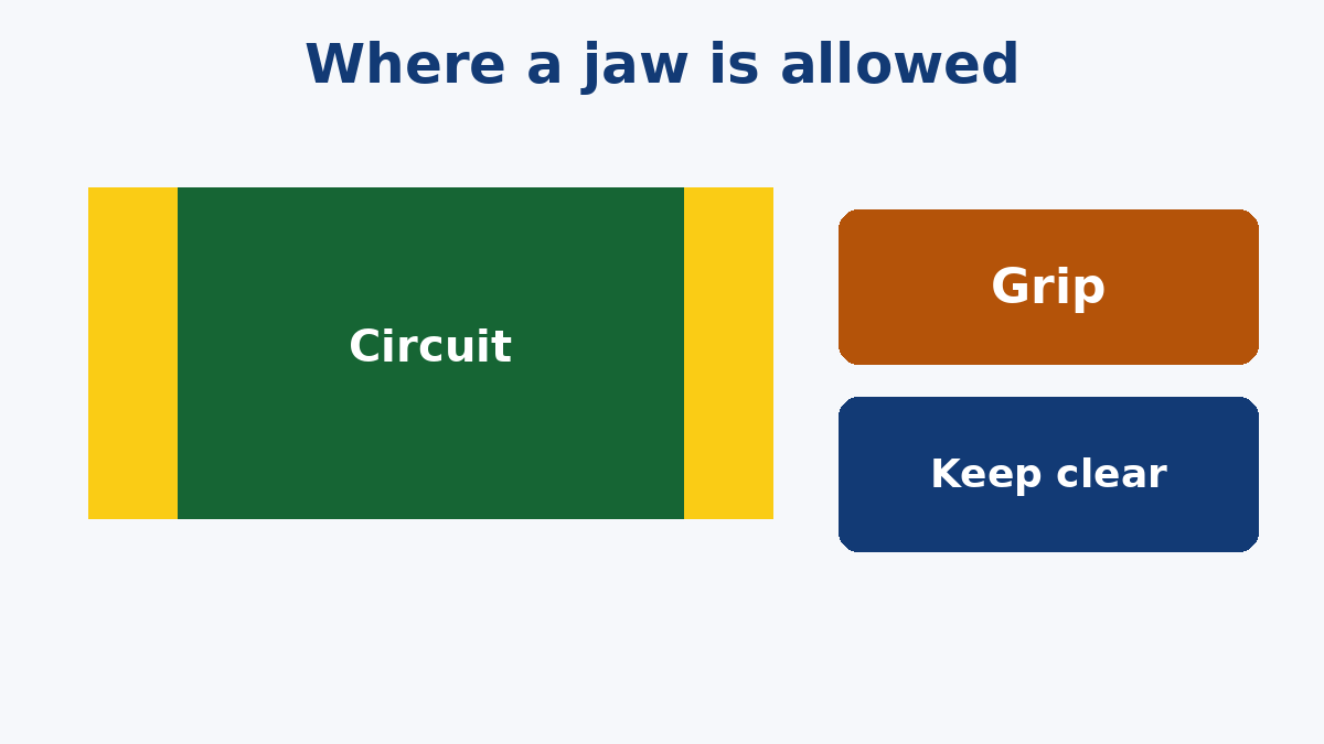
The grip needs an empty strip
Jaws close on the edge. If that edge is a row of parts, a gold finger, an NFC coil, or the only test pad, the holder becomes the defect. Crushed mask, a cracked ceramic body, a finger you can no longer plug in, a coil pulled off tune.
Mark a grip zone on the assembly drawing: which edges, and that components, copper that must stay pretty, and anything tuned stay out of it. Do not leave the zone as "the edge." People will clamp the edge that is closest to the joint they are soldering, which is also where the parts are. Soft rubber on the jaw stops a scratch. It does not stop a point load on a capacitor that sits under the pad. Keep those parts off the jaw line. The same bending that cracks them during depaneling will crack them in a vise if the board is bowed between two hard points.
A flip frame that rotates the board for the second side is a hand-solder tool. It is not how a double-sided reflow build is held. Reflow wants the board flat, the paste untouched by a clamp, and the fiducials visible to the machine. Our SMT PCB Assembly page is that path: stencil, placement and reflow, with the fiducials and the paste in the review before the line starts. Tape, a clamp or a cover that hides a fiducial or lands on a pad is a hold-down that deleted the alignment. If the only flat region is a process rail, the rail is what gets clamped, and the rail is scrap. Say that in the panel note. Clamping the finished outline means the product edge is the fixture edge.
Holes locate. Jaws only squeeze
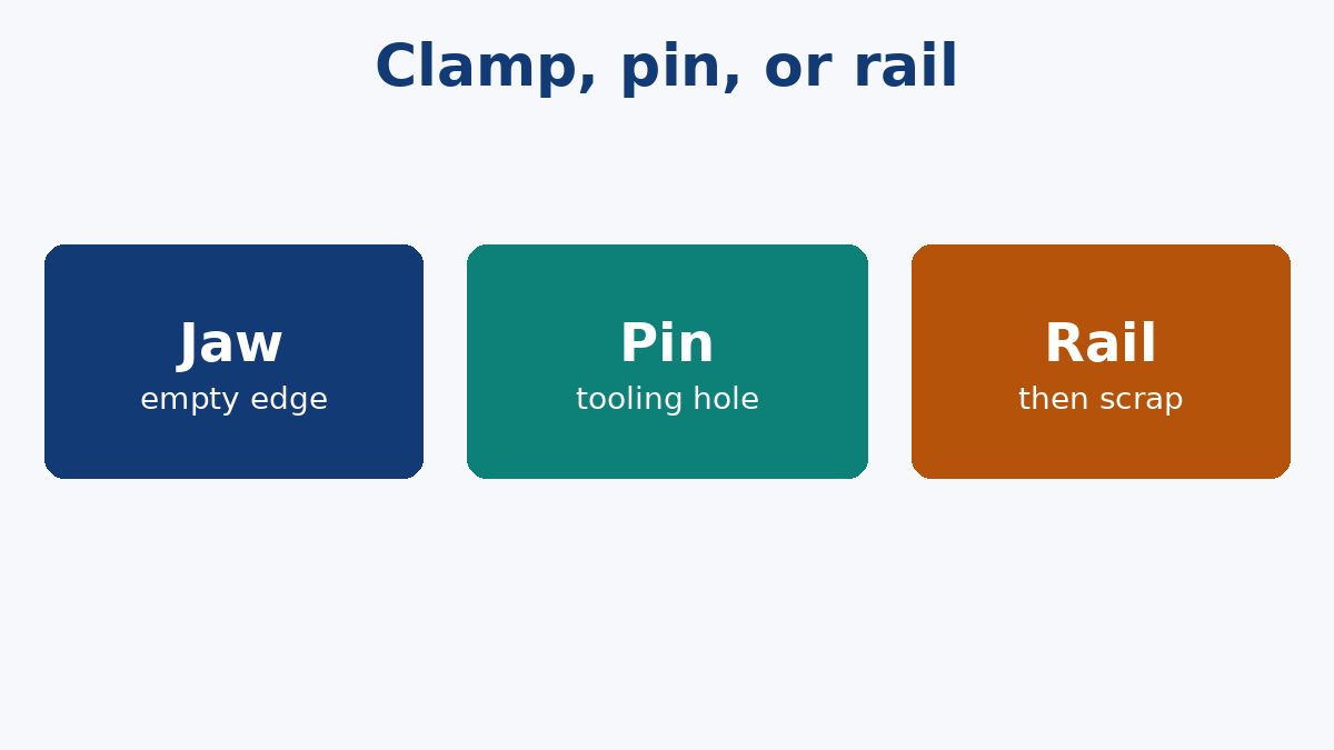
A vise does not know where the board is, only that it is tight. A fixture that has to repeat — paste print, a press-fit pin, a bed of probes — locates on holes or on tooling pins in the panel. Those holes belong on the fabrication drawing: which ones, plated or not, and which side the pin enters.
An unplated tooling hole is a mechanical feature. Plate it and a metal pin becomes a short into whatever net you tied to the barrel. Do not plate tooling holes unless the pin is supposed to be a contact, and then it is a test point, not a tooling hole. Do not add the holes on the bench with a drill after the board is built. The glass and the copper were not designed for that, and the location will not match the fixture that was made from the file.
Flex does not belong in a rigid vise
A flex circuit in a bench vise takes a bend wherever the jaws and gravity decide. That bend is not the bend on the drawing, and it is often tighter. Our Flexible PCB page includes a review of the bend area for circuits that have to move or fold on purpose. A holder that folds them by accident is not that review.
Flex that is going through placement needs a carrier that keeps it flat: pins or a pocket, and hold-down that does not cover pads, fiducials or the bend you still care about. Tape is a hold-down. It is also a residue. Keep it off gold and off lands. A rigid board's edge clamp is the wrong picture to copy onto a flex tail.
The bench, briefly
For one board and an iron, a clamp with soft jaws and a way to tilt is enough, if the empty strip exists. A metal vise on an assembled board is also a conductor. A static-sensitive part does not care that you were careful with the iron if the jaw was the discharge. Use a grounded wrist strap and an ESD mat when the board is populated, and do not slide finished assemblies across a bare metal jaw.
A rack that holds several boards for drying or inspection should hold them apart. Wet boards stacked in a clip transfer flux from one to the next and bend the lower one. That is storage, not a process.
None of this requires a particular brand of holder. It requires the drawing to show where a jaw, a pin or a rail is allowed to touch, and the files to include the holes those pins use. If the grip zone is missing, the person at the bench will invent one, and the invention will be on top of a part.