
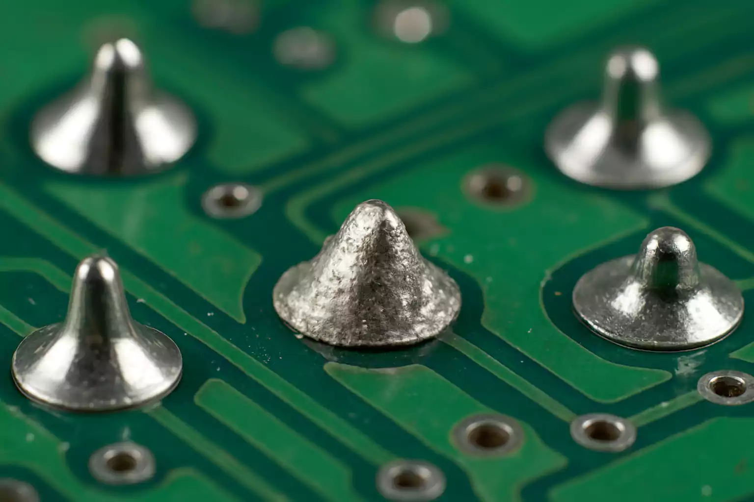
Procurement and quality teams often discover cold solder joints only after a board passes a quick power-on test and then fails in the field. A cold solder joint is a solder connection that never formed a reliable metallurgical bond between the pad and the lead (or termination)--usually because heat, cleanliness, or wetting fell short during soldering. The joint may look "almost right," measure continuity on a bench, and still open under vibration, thermal cycling, or current load.
For overseas PCB/PCBA buyers, cold joints are not a hobbyist tip list. They are an acceptance, process-control, and rework-ownership problem: who inspects to which IPC class, which reflow or wave window was locked, and what the assembler must do when AOI or X-ray flags a dull, poorly wetted fillet.
Buyer acceptance: what you should lock before SMT starts
Write cold-joint risk into the quality plan, not into a hope that "the factory will check." Useful RFQ language names:
- Visual acceptance reference (commonly IPC-A-610 Class 2 or Class 3) and whether workmanship photos ship with first articles
- AOI coverage on SMT side(s), including whether 3D height/volume measurement is in scope for critical pads
- Reflow alloy and profile ownership (paste datasheet + board-mass first-article profile)
- Sample vs 100% electrical coverage after assembly, and whether intermittent fails trigger rework or scrap
- Rework limits: how many heat cycles a pad or package may see before the joint is condemned
If those items stay blank, two China PCBA quotes are not comparable. One shop may catch cold fillets on AOI and reflow them under a documented process; another may ship boards that only fail after shipping vibration.
What a cold solder joint is (and what it is not)
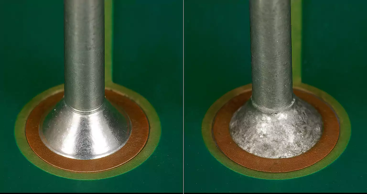
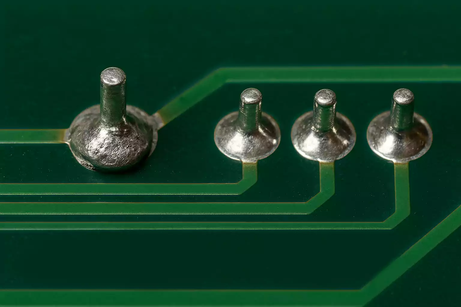
In production language, a cold joint means the solder did not fully melt and wet both surfaces long enough to form a continuous intermetallic bond. Typical visual cues include a dull or grainy surface, a ball-like shape with a contact-angle problem (poor wetting), incomplete pad coverage, or a hairline ring crack at the lead after cool-down. Electrically, resistance can be high, unstable, or intermittent when the board flexes.
Do not confuse cold joints with every other solder complaint:
- Cracked joints often started as acceptable fillets and later fractured from mechanical stress or CTE mismatch.
- Dry or non-wet joints share the "never bonded" root cause family, but buyers and process engineers usually reserve "cold" for heat/time/wetting shortfalls rather than pure contamination alone.
- Fatigue failures appear after many thermal or vibration cycles on joints that once met workmanship criteria.
Naming the defect correctly changes the corrective action: a reflow profile fix differs from a board-flex fixture fix or a paste-print volume fix.
How cold joints form on real SMT and hand lines
Reliable soldering needs heat into the pad and termination, clean metal, active flux, and undisturbed solidification. Cold joints appear when any of those fail:
- Underheated joints: iron tip too cool, reflow peak or time-above-liquidus too short for board copper mass, or large ground pours stealing heat from small pads.
- Contaminated or oxidized surfaces: aged OSP, fingerprint oils, paste beyond shelf life, or insufficient flux activity--especially painful with lead-free alloys that wet less forgivingly than SnPb.
- Motion during solidification: operator nudge, conveyor vibration, or fixture shift while the fillet is pasty.
- Process mismatch: hand-solder touch-up on a pad that never reached reflow temperature, or selective solder that underheats tall connectors next to heavy copper.
Lead-free SAC alloys raise the practical risk. Higher liquidus and poorer wetting mean a profile that "worked on the evaluation board" can underheat a production panel with thick copper and still look shiny enough to fool a rushed visual check.
Factory controls that actually reduce cold joints
Buyer-facing prevention is process evidence, not slogans:
- Paste print control -- SPI (solder paste inspection) catches starved deposits before placement. Cold joints after reflow often start as insufficient paste or poor release on fine pads.
- Reflow ownership -- First-article profiling with thermocouples on high-mass and sensitive packages. Peak temperature and time above liquidus must follow paste and component limits for that board, not a generic oven recipe.
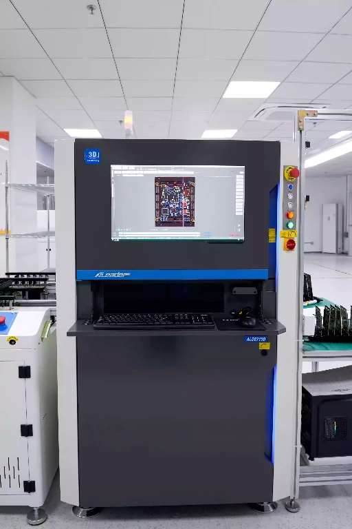
- AOI with criteria -- 2D AOI finds missing solder and gross shape errors; 3D AOI helps on fillet height and volume for many SMT packages. Critical through-hole or connector joints may still need targeted visual or selective X-ray.
- Handling discipline -- No flexing hot panels; fixtures that hold connectors during wave or selective solder; documented cool-down before test fixtures clamp the board.
- Materials discipline -- In-date paste, correct flux chemistry for the finish (ENIG, HASL, OSP), and clean storage so pads are solderable when the line runs.
IPC-A-610 remains the common visual language between buyer and CM. Class 2 vs Class 3 changes how much cosmetic and wetting allowance you accept--and therefore how aggressive the AOI fail thresholds should be.
Identification: visual, electrical, and advanced
Visual (magnifier or AOI): dull/grainy surface, incomplete wetting, irregular fillet, ring cracks, solder that sits as a blob instead of climbing the lead. On fine-pitch SMT, rely on AOI programming more than naked-eye sampling.
Electrical: continuity that changes when you press a lead, elevated joint resistance, or functional fails that disappear when a connector is reseated. Intermittent field fails after vibration or thermal soak are classic cold-joint signatures--even when ICT passed once at room temperature.
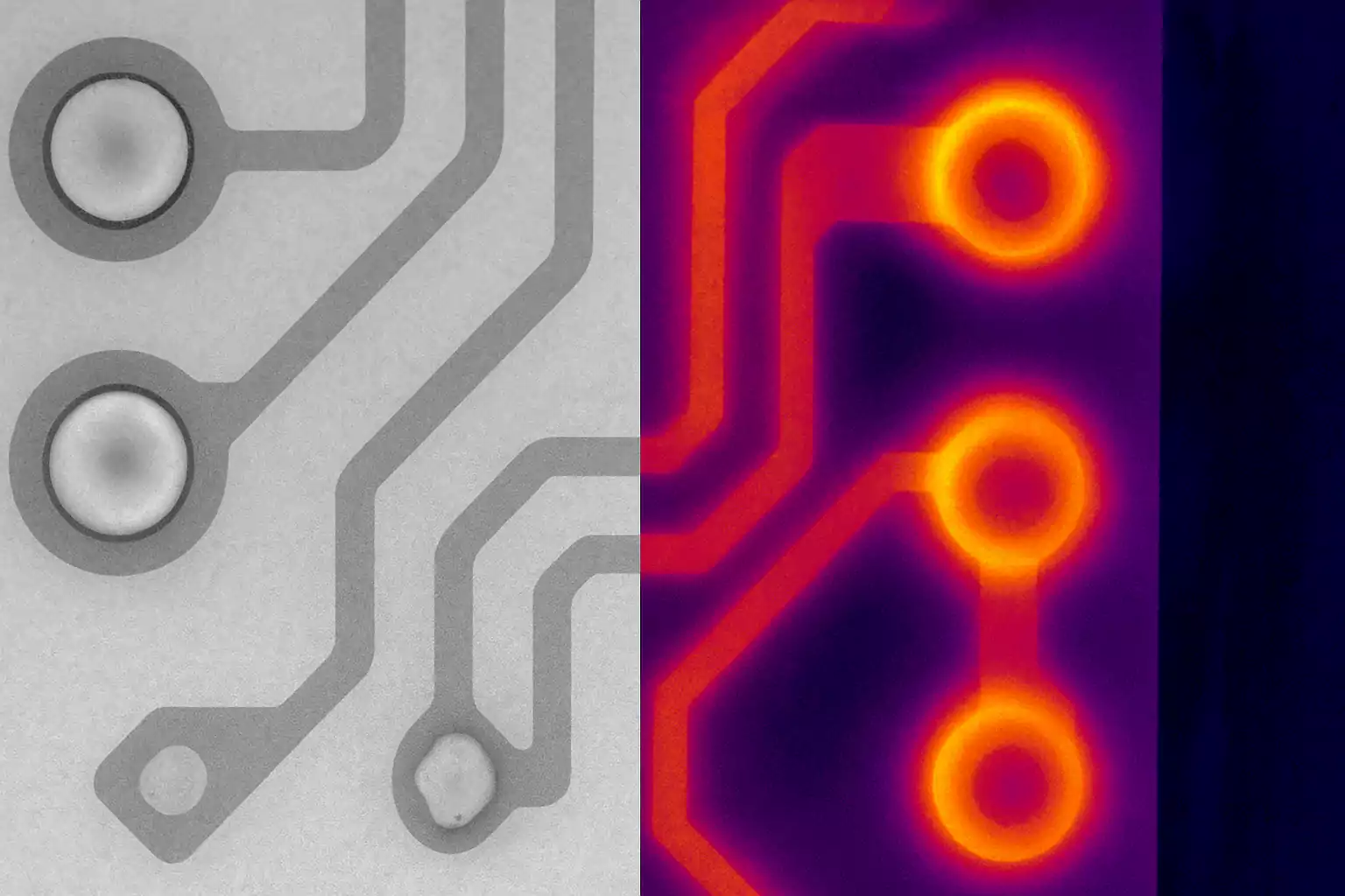
Advanced: X-ray for hidden joints (BGA, QFN thermal pads), thermal imaging for localized heating at high-resistance joints, and microsection for supplier disputes or Class 3 evidence. Use advanced methods when risk or package type makes optical acceptance incomplete.
Consequences buyers feel in the field
Cold joints raise contact resistance, create intermittent opens, and invite complete open circuits after mechanical or thermal stress. Consumer products may "glitch"; automotive, industrial, medical, and telecom hardware can lose sensors, control loops, or links with much higher cost. Because the joint can pass a short functional test, the defect often escapes prototype enthusiasm and shows up in warranty or burn-in.
Rework that restores a metallurgical bond
Repair is usually straightforward when pads and finishes survive the heat:
- Confirm the suspect joint under magnification and, if needed, with a continuity check that reproduces intermittency.
- Stabilize the board and component so nothing moves during reflow.
- Add fresh flux; remove oxidized or insufficient solder with braid if the fillet is contaminated.
- Reheat pad and lead together with a controlled iron or hot-air nozzle set for the alloy; allow full wetting.
- Add a small amount of fresh solder if volume was low; form a smooth, properly wetted fillet.
- Cool without disturbance; clean flux residues per the process; re-inspect to the same IPC criteria used for production.
Limit rework cycles on fine pads and high-value packages. Document which serials were reworked so field analysis stays honest.
Industry risk snapshot (buyer view)
| Segment | Typical risk if cold joints escape | What buyers usually demand |
|---|---|---|
| Consumer / IoT | Medium -- returns, brand damage | IPC Class 2, AOI, sample functional |
| Industrial controls | High -- downtime, nuisance trips | AOI + thermal/vibration screening on critical lots |
| Automotive | High -- safety-related ECUs/sensors | IPC Class 2-3 intent, AOI/X-ray, process PPAP discipline |
| Medical / aerospace | Very high -- patient or mission impact | Class 3 workmanship, higher inspection coverage, traceability |
| Telecom / networking | Medium-high -- intermittent link errors | Reflow control, AOI, targeted X-ray on dense packages |
Standards and audit schemes (IPC-A-610, IATF, ISO 13485, AS9100, and similar) do not magically remove cold joints; they force process evidence and acceptance clarity. Put that evidence on the traveler, not only in a brochure.
Practical takeaway for RFQ and first article
Treat cold solder joints as a named process risk: paste volume, heat into the joint, wetting chemistry, undisturbed solidification, and inspection criteria. Ask for AOI (and 3D where it matters), first-article profile records, IPC class, and rework rules. Boards that only "power on" at the dock are not proven solder joints--especially after overseas shipping vibration and the first thermal cycle in your enclosure.