

Overseas buyers sourcing high-reliability boards in China often ask for an "aviation PCB" as if that were a single catalog part number. It is not. A commercial aviation PCB is a printed circuit board intended for civilian passenger or cargo aircraft electronics--flight control, navigation and communication, engine and power monitoring, cockpit displays, or cabin systems--where reliability, documentation, and change control matter more than consumer-grade cost optimization.
This guide separates commercial aviation PCBs from broader aerospace and avionics labels, maps where boards sit in the aircraft, explains how requirements are derived, and gives procurement and engineering teams RFQ language that separates real fab capability from brochure claims. XFPCB supports high-reliability multilayer, HDI, rigid-flex, RF, and high-current builds for aviation-adjacent and industrial programs when drawings and acceptance criteria are clear--without claiming every bare board is "DO-160 certified" or that an AS9100 QMS stamp equals part-level certification.
Commercial aviation PCB vs aviation, aerospace, and avionics
Use precise language on RFQs. Vague labels invite mismatched quotes.
| Term | Practical scope for buyers |
|---|---|
| Commercial aviation PCB | Civilian passenger and cargo aircraft electronics and related ground/support electronics when the drawing says so |
| Aviation PCB | Civil and/or military aircraft electronics--ask which |
| Aerospace PCB | Aircraft plus satellites, launch vehicles, and other space systems--much wider process and material set |
| Avionics PCB | Flight-related electronics (control, nav, comm, instrumentation)--a function label, not a fab process by itself |
Commercial aviation boards sit inside the aerospace family, but the material stack-up, plating, inspection, and documentation you need depend on the equipment, installation zone, and customer specification--not on the word "aerospace" alone.
Where PCBs are used in commercial aircraft
PCB construction follows the system role and environment, not a one-size "aircraft FR-4" recipe.
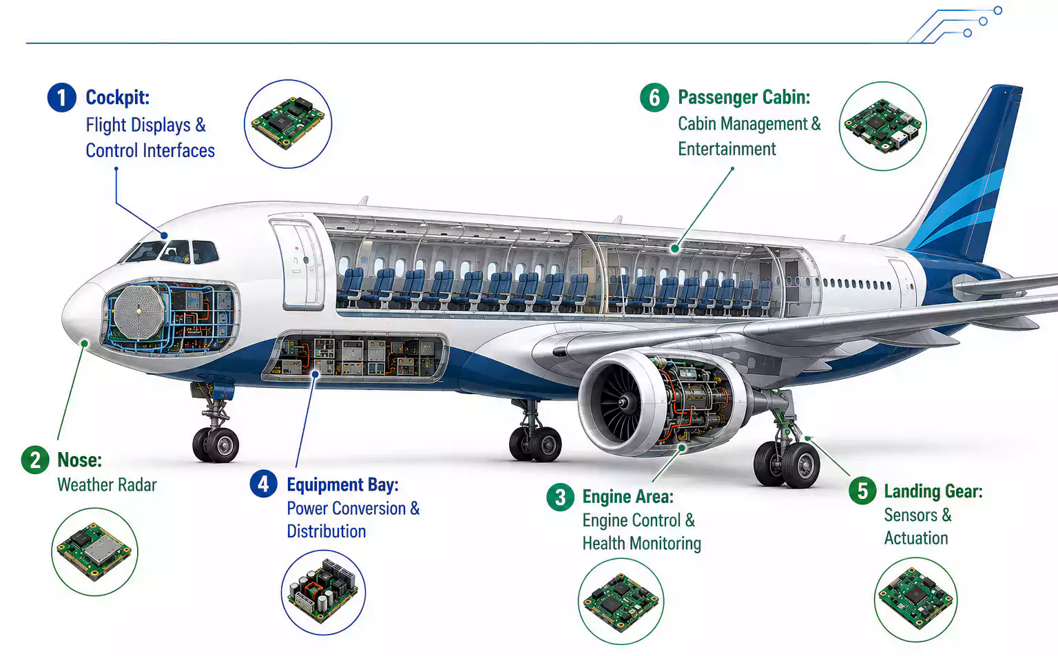
Flight control and core avionics
Flight control computers, autopilot, air-data interfaces, sensor conditioning, actuator drives, and warning logic need stable timing, clean power delivery, and interconnects that survive long service life. Redundancy is an equipment architecture decision; the PCB must still meet the design authority's margins for impedance, via reliability, and workmanship class.
Engine, fuel, and power distribution
Engine monitoring, fuel gauging, power conversion, distribution, and landing-gear related electronics often see higher vibration and temperature swing. High-current paths need copper capacity, voltage-drop budgets, creepage/clearance at altitude, connector mechanical support, and thermal paths that do not rely on hope.
Navigation, communication, and radar
GNSS, inertial interfaces, radios, data links, weather radar, and antenna front-ends push controlled impedance, low-loss dielectrics, return-path continuity, shielding, and careful connector/via transitions. Treat RF stack-ups as named materials with Dk/Df windows--not as "FR-4 equivalent" substitutions without approval.
Cockpit and cabin electronics
Displays, instruments, cabin management, IFE, seat power, and lighting range from dense HDI breakout around fine-pitch BGAs to cost- and weight-sensitive cabin boards. Cockpit hardware usually emphasizes SI/thermal discipline; cabin hardware still needs controlled manufacturing when airlines demand long support life.
| Aircraft system | Common PCB technology | Primary engineering focus |
|---|---|---|
| Flight control | Multilayer or HDI | Reliability, SI, workmanship class |
| Nav / radar / RF links | RF or hybrid multilayer | Loss, impedance, EMI |
| Cockpit displays | HDI | Fine-pitch routing, thermal |
| Engine / mechanical bay | Multilayer or rigid-flex | Temperature, vibration |
| Power distribution | Heavy copper / high-current | I2R rise, spacing, heat |
| Cabin electronics | Multilayer | Size, weight, cost, maintainability |
Aviation-grade expectations vs standard commercial PCBs
Here "standard commercial" means consumer or general industrial electronics--not commercial aircraft.
| Topic | Commercial aviation / high-reliability intent | Typical standard commercial PCB |
|---|---|---|
| Environment | Temperature cycling, vibration, altitude, moisture, EMI may all apply | Mostly benign office/home or mild industrial |
| Reliability posture | Low failure tolerance, long service life | Cost/life tradeoffs dominate |
| Materials and process | Named laminates, stack-up lock, plating and lot records | Commodity materials often enough |
| Traceability / change | Lot records, PCN discipline, approved substitutes | Light change control |
| Inspection / test | Impedance coupons, microsection, FAI packages when required | Netlist electrical + basic visual |
| Lifecycle | Obsolescence planning over years | Short product cycles |
Do not paste "IPC Class 3 + polyimide + heavy copper + conformal coat" onto every RFQ. Specify only what the design authority and environment require; over-specifying raises cost without raising fitness for use.
How requirements should be defined (before you send Gerbers)
Three inputs drive almost every real acceptance line:
1. System criticality
Define function, failure effect, redundancy expectations, and what "still safe/operable" means after a fault. That drives design margins, documentation depth, and whether Class 2 visual acceptance is even appropriate.
2. Installation environment
Cabin racks, pressurized electronics bays, landing-gear adjacent zones, and engine-proximate areas impose different temperature, vibration, humidity, contamination, and airflow assumptions. Ask engineering for the environmental envelope--not a marketing adjective.
3. Electrical and mechanical loads
Voltage, current, dissipation, frequency content, altitude, connector loads, and mounting method become copper weight, spacing, stack-up, and fixture rules. Convert those into drawing notes and procurement specs buyers can quote apples-to-apples.
Environmental stress and failure mechanisms buyers should name
| Stress | Typical PCB/assembly failure mode | Engineering response |
|---|---|---|
| Temperature cycling | Via fatigue, solder fatigue, delamination | Material CTE/Tg match, via design, reliable plating |
| Vibration / shock | Connector and heavy-part failures | Strain relief, adhesive/staking, mechanical support |
| Altitude / pressure | Reduced dielectric margin, discharge risk | Creepage/clearance vs altitude and voltage |
| EMI / RFI | Crosstalk, sensor and radio errors | Planes, filtering, shielding, return paths |
| Moisture / contamination | Leakage, corrosion | Cleanliness limits, coating when required |
Temperature cycling stresses copper-resin CTE mismatch. Vibration fails parts that only solder was holding. Altitude shrinks insulation margin. Poor EMI design shows up as "mystery" avionics faults. Residual ionic contamination undermines even good layouts--ask for cleanliness criteria when coating or high-impedance circuits are in play.
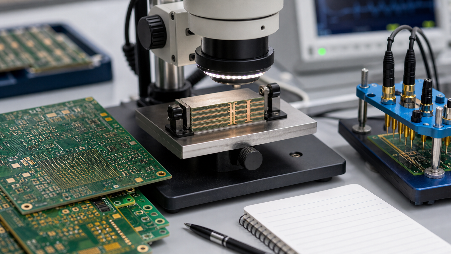
PCB technologies used in commercial aviation electronics
| Technology | Typical use | Buyer watch-outs |
|---|---|---|
| Multilayer rigid | Control, processing, power, displays | Locked stack-up, impedance coupons, plane strategy |
| HDI | FPGAs, fine-pitch BGAs, compact modules | Microvia reliability, via fill, sequential lamination capability |
| Flex / rigid-flex | Dense interconnects, harness reduction | Bend radius, coverlay, stiffeners, transition zones |
| RF / microwave | Nav, comm, radar front-ends | Named low-loss materials, roughness, shield cans |
| High-current / thermally enhanced | Power conversion and distribution | Copper weight, temp rise, board weight, connectors |
HDI and rigid-flex can cut connectors and mass, but they raise registration, plating, and mechanical DFM risk. Ask for evidence on similar constructions--not only a capability matrix checkbox.
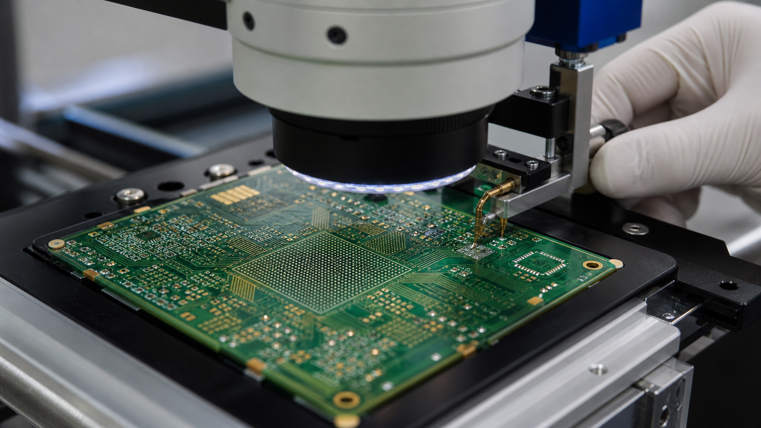
Materials, SI/PI, and thermal
Useful RFQ questions:
- Laminate family, Tg, Td, and Z-axis CTE windows--and whether substitutes need written approval
- Dk/Df targets and copper foil type for RF or high-speed nets
- Moisture absorption expectations for the installation zone
- Controlled-impedance nets, reference planes, and coupon requirements
- Decoupling and PDN notes that manufacturing must not "optimize away"
- Thermal vias, chassis conduction, and keep-outs for heat paths
- Mechanical support for heavy magnetics and connectors
High-Tg FR-4 may be enough for many digital modules; low-loss ceramics/hydrocarbons or polyimide appear when RF loss or flex construction demands them. Force the drawing to name the material--do not accept "equivalent" without engineering sign-off.
Manufacturing, assembly, and traceability that belong on the PO
For aviation-adjacent and high-reliability programs, treat the traveler as part of the product:
- Verified laminate lots and dielectric thickness control
- Layer registration and lamination records
- PTH / microvia plating process capability and, when required, microsections
- Impedance reports tied to the revision you ordered
- First-article packages when the customer drawing requires them
- Component lot/date-code tracking, counterfeit-avoidance process, and PCN/EOL handling for long-life BOMs
- Assembly inspection mix: SPI, AOI, X-ray for hidden joints, cleanliness/ionic limits, and functional test ownership
China fabs vary widely here. The discriminating questions are: Can you freeze the stack-up? Will you refuse silent material swaps? What serial-level records ship with the lot? Brochure photos of certificates do not answer those.
Standards: correct scope (and myths to kill on the RFQ)
| Standard | What it actually governs |
|---|---|
| AS9100 | Organization-level aviation/space/defense quality management system--not a per-board product certificate |
| IPC-6012 | Rigid PCB performance/qualification classes for bare boards |
| IPC-A-610 | Acceptability of electronic assemblies (soldering/workmanship)--not bare fab alone |
| J-STD-001 | Soldering materials and process requirements for assemblies |
| RTCA/DO-160 | Environmental conditions and test procedures for airborne equipment |
| Customer drawing / SCD | The binding design, fab, assembly, test, and documentation rules for your part |
Critical buyer caveats:
- AS9100 at a supplier means their QMS was audited for aerospace intent. It does not mean every panel they etch is "AS9100 certified hardware."
- DO-160 qualifies airborne equipment under defined environmental categories. It does not mean every bare PCB was DO-160 tested, and asking a fab to "DO-160 certify the bare board" without an equipment-level plan is usually a category error.
- IPC-A-610 Class 3 is an assembly acceptance choice. Pair it with the right bare-board performance class (often via IPC-6012 language on the fab drawing) instead of hoping one acronym covers both.
- Always let the design authority name applicable standards, classes, environmental categories, and deliverable documents. XFPCB will follow the drawing and PO--we will not invent certification claims that the program does not require or that a bare-board process cannot honestly support.
RFQ acceptance criteria that work for overseas sourcing
Put measurable lines on the quote package:
- Exact part number, revision, and whether fab-only, kit, or turnkey assembly is in scope
- Laminate callouts and "no unauthorized substitute" language
- Impedance nets, coupon requirements, and report format
- Bare-board performance class / IPC-6012 intent if required by engineering
- Assembly workmanship class (IPC-A-610) and soldering standard (J-STD-001) when assembling
- Traceability depth: material lots, component date codes, traveler retention period
- Inspection list: electrical test, AOI, X-ray sample or 100%, microsection on first article if needed
- Change-control rule: written approval before material, stack-up, or process changes
- Explicit non-claims: do not ask the fab to stamp DO-160 or AS9100 on the bare board unless your quality organization has a defined, honest interpretation
Those lines make China quotes comparable and protect programs that are aviation-adjacent or high-reliability without pretending every board is flight-critical certified hardware.
Conclusion
Commercial aviation PCBs succeed when criticality, environment, and electrical/mechanical loads are translated into locked materials, constructions, inspection, and traceability--then enforced on the PO. Broader aerospace marketing language is a weak substitute for a clear drawing package.
For overseas procurement and engineering teams, the winning habit is specificity: name the system, name the stresses, name the standards with correct scope, and reject silent "equivalents." XFPCB can manufacture and assemble high-reliability multilayer, HDI, rigid-flex, RF, and power boards against those written criteria for aviation-adjacent and industrial programs--matching capability to the drawing, not to a slogan.