
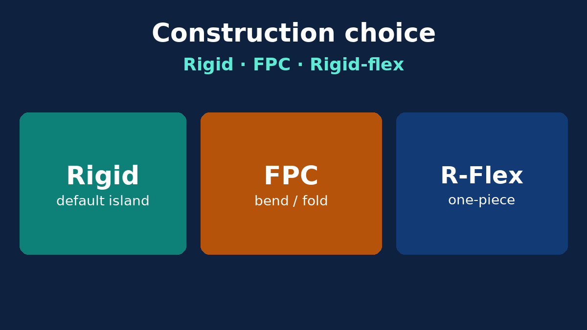
Choosing between a rigid board, a flexible circuit (FPC), and a rigid-flex stack is a construction decision, not a brochure comparison of “hard vs soft.” Overseas buyers and engineers who RFQ the wrong build type pay for it in EQ loops, connector redesigns, stiffener respins, and assembly yield—not in a tidy line-item that says “wrong material.” This article frames the selection for procurement and hardware leads: when rigid is enough, when FPC earns its process complexity, when rigid-flex is the honest answer, and what must appear on drawings so a China fab does not reinterpret your transitions. It is not a bend-life or coverlay deep dive; those topics matter after you have already chosen the right construction family.
Buyer decision frame: three questions before the RFQ
Before you ask for quotes, answer three questions in writing:
- Does the product need dynamic flex (repeated bending in use), static flex (bend once for install), or no flex (only packaging and connectors)?
- Where do connectors and components need a stiff, solderable island—and can that island be a separate rigid PCB plus cable/FPC, or must it be one inseparable assembly?
- Who owns the transition—your layout team with a rigid-flex stack note, or a cable house with an FPC jumper between two rigid boards?
If flex is only “it might be nice for packaging,” start with rigid plus connectors or a simple FPC jumper. Rigid-flex is powerful and expensive in process steps; it is not a default upgrade. If you already know you need Flexible PCB or Rigid-Flex PCB capability, name that construction on the RFQ cover sheet so CAM does not quote a rigid multilayer by mistake.
When rigid PCB is the right construction
Rigid FR-4 (and related rigid laminates) remains the default for most controllers, power boards, compute modules, and industrial I/O. Choose rigid when:
- The outline fits the enclosure without needing to fold the circuit through a hinge or around a battery.
- All connectors can sit on one board or on boards joined by cables you are willing to source and assemble.
- Mechanical loads (screw bosses, standoffs, heavy transformers) need a stiff dielectric and thick copper options that flex constructions handle poorly.
- The program needs fast EQ and broad fab capacity—rigid multilayer process is the most mature path in high-volume China manufacturing.
Cost traps on the rigid side are familiar: over-layering “just in case,” gold where ENIG would do, and HDI creep when a connector redesign would have kept through-hole vias. Those traps are still cheaper than accidentally specifying rigid-flex because a salesperson said flex was trendy. Use rigid when the product does not move the circuit after install.
When FPC (flexible circuit) is the right construction
FPC earns its place when the circuit itself must bend, fold, or snake through a thin envelope—cameras, displays, wearables, battery interconnects, and dense module-to-module links inside small housings. Typical buyer gates:
- Space: no room for a board-to-board connector stack or a ribbon that still needs strain relief you cannot package.
- Weight and thickness: polyimide flex can be thinner than a rigid board plus connector.
- Static bend for assembly: fold once behind a display; then the flex stays put.
- Dynamic flex: hinges and sliding mechanisms—only with a flex stack designed for that life, coverlay openings, and copper treatment appropriate to bending (still without inventing cycle counts here; freeze the life requirement with your reliability owner).
FPC is not “soft FR-4.” Adhesiveless or adhesive polyimide systems, coverlay vs flexible solder mask, stiffened zones for parts, and controlled impedance on flex all change the fab traveler. Buyers who paste a rigid stack note onto an FPC RFQ create immediate EQ. Call out construction: layer count, copper type (RA/ED as required by bend), coverlay openings, stiffener material and thickness, and which zones are bendable vs component islands.
When rigid-flex is the right construction
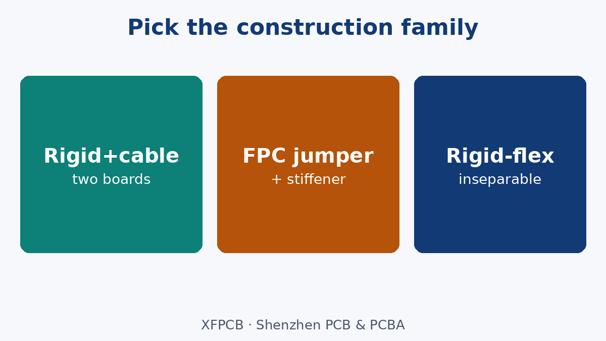
Rigid-flex combines rigid laminated zones and flexible zones in one inseparable part. Choose it when:
- Connectors and BGAs need rigid pads and reliable SMT, and the same circuit must flex through a hinge or wrap without a separable connector in that path.
- Reliability or sealing requirements reject a board-to-board connector in a wet, vibrating, or sealed cavity.
- Assembly labor and connector Z-height dominate cost more than the rigid-flex process premium.
- Signal integrity or shielding needs continuous reference across the transition without a connector discontinuity.
Do not choose rigid-flex merely to reduce BOM line count if a well-designed FPC jumper between two rigid boards meets reliability and packaging. Rigid-flex multiplies stack documentation, book-build (where used), coverlay/rigid mask transitions, and panelization constraints. It is the right hammer for hinged or folded one-piece assemblies—not a substitute for connector strategy.
Transitions, stiffeners, and connectors: where programs fail
Most selection failures are not “picked FR-4 instead of polyimide.” They are transition and mechanical attach failures:
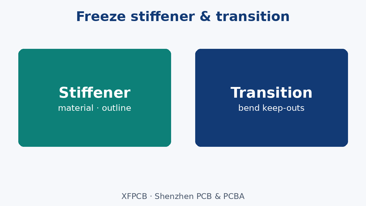
Transition zones (rigid-flex). The rigid-to-flex boundary needs clear keep-outs: no vias in the bend region, controlled copper, and stack notes that name which layers continue into the flex. Ambiguous transitions cause CAM to guess layer drop schedules—or reject the job. Put transition geometry on the mechanical drawing with dimensions, not only in a 3D CAD screenshot.
Stiffeners (FPC). Polyimide alone rarely supports connectors or arrays of parts. Polyimide, FR-4, or stainless stiffeners under connector footprints are common. Call out stiffener outline, thickness, adhesive type if relevant, and whether the stiffener is selective or full-area. Missing stiffener callouts produce assemblies that crack pads at the connector during mate cycles.
Connectors. Board-to-board, FPC-to-board (ZIF/LIF), and soldered flex tails each imply different stiffener and pad geometries. A ZIF that needs a specific tail thickness will fail if the fab builds a different coverlay stack. Freeze connector P/N, tail length, and stiffener stack together—never separately across three emails.
Strain relief. Whether rigid, FPC, or rigid-flex, the enclosure must support the flex or cable so solder joints are not the hinge. Drawing notes that ignore chassis clips invite field failures the fab cannot plate away.
Process and cost traps (no invented prices)
Without quoting dollars, these traps repeatedly inflate landed cost and schedule:
- Specifying rigid-flex when an FPC jumper + two rigid boards would work—extra lamination complexity and longer EQ for little packaging gain.
- Specifying bare FPC for a connector island without a stiffener—assembly scrap and connector rework.
- Copying a rigid impedance stack onto flex without checking dielectric and coverlay heights—the coupon and the bent region will not match.
- Dynamic flex called out with a static-flex copper stack—early copper crack; reliability owner must freeze life and copper construction together.
- Gold fingers or ENIG on flex tails without wear/mate intent—finish vanity on the wrong problem.
- Panelization ignored—flex and rigid-flex panels waste differently than rigid arrays; ask the plant how units nest before you freeze outline for “panel efficiency” assumptions.
- Late construction change—switching from rigid+cable to rigid-flex after SMT programs exist resets stencil, fixtures, and travelers.
China fabs can build all three families; they cannot cheaply undo a construction mischoice after NRE and first-article. Select early; freeze early.
Failure modes buyers actually see
Map symptoms to construction mistakes:
- Pad cratering or trace crack at connector on FPC — missing or underspecified stiffener; bend too close to solder joints.
- Open in hinge region after cycles — dynamic flex on a stack meant for static fold; copper type or coverlay opening wrong.
- Warpage / coplanarity fail on rigid-flex rigid island — unbalanced copper or asymmetric stack across the rigid zone.
- ZIF insertion failure — tail thickness or stiffener length outside connector window.
- EMI or SI regression after replacing connector with flex — return path and shield strategy changed; not a “flex is noisy” slogan—check reference continuity across the transition.
- Assembly cannot fixture the part — outline and stiffener create a floppy panel the SMT line was not tooled for.
Fab can adjust coverlay openings and stiffener outlines within EQ when drawings allow. Fab cannot invent a hinge life requirement you never wrote, or turn a two-board + cable architecture into rigid-flex without a new design package.
What fab can and cannot fix
Can follow when called out: layer drop / book-build per stack note; coverlay openings; stiffener material and outline; controlled impedance coupons on the correct construction; selective surface finish on stiff zones vs flex tails; panelization suggestions for yield.
Cannot fix after Gerbers are frozen: wrong construction family for the packaging concept; bend radius forced by enclosure smaller than the stack allows; connector footprint that assumes a stiffener you never ordered; missing keep-outs in the bend region filled with vias.
If EQ discovers the enclosure needs a fold you did not design for, the honest path is a construction ECO—not a plea to “make the FR-4 bend a little.”
RFQ and drawing callouts that lock the selection
Put construction identity on the cover sheet and fab note:
- Construction class: rigid / FPC / rigid-flex (one primary class per part number).
- Stack table with materials for rigid and flex zones; which layers continue through flex.
- Bend regions: static vs dynamic intent; keep-out for vias and components; minimum bend guidance from your mechanical owner (do not invent plant-wide mm tables in marketing copy—freeze your number on the drawing).
- Stiffener: material, thickness, outline, side, and adhesive notes as required.
- Coverlay / mask: openings for pads, PSA areas, and PSA vs soldered attach.
- Connectors: P/N, tail geometry, plating in mate zone.
- Impedance: reference layers and coupon location on the actual construction.
- Accept criteria: which zones get flying probe / AOI emphasis; cosmetic class on exposed flex.
Also send mechanical drawings with transition dimensions and a short English readme. Ambiguous “flex PCB like phone cable” language produces wrong quotes. For manufacturing file discipline shared across constructions, keep Manufacturing Files expectations aligned with the stack note you freeze.
Common EQ loop on construction selection
A familiar overseas cycle:
- Team quotes rigid because it is familiar.
- Enclosure arrives; board will not fit without a fold or a second board.
- Late switch to FPC jumper—or jump straight to rigid-flex—without stiffener and transition drawings.
- First articles fail ZIF fit or crack at the connector.
- Second EQ finally freezes stiffener, coverlay, and bend keep-outs—work that belonged in the first RFQ.
Break the loop with a one-page construction decision memo attached to the RFQ: rigid vs FPC vs rigid-flex, why, and the mechanical attach plan. Plants quote what you name. If you name nothing, they assume rigid multilayer.
Assembly and fixture implications
Construction choice is also an SMT and fixture choice. Rigid panels use standard carriers. FPC often needs fixtures, stiffener-down orientation rules, and careful thermal profiles so thin polyimide does not warp under reflow. Rigid-flex needs fixtures that support rigid islands while protecting flex tails from solder splash and handling damage. Call assembly construction on the PCBA RFQ the same day you freeze fab construction—do not let fab ship a limp flex into an assembly line that expected a rigid array. If turnkey is in scope, state whether the fab and the assembler share one traveler or two; split ownership is where stiffener notes get lost.
What we are not claiming
No universal price ranking of rigid vs FPC vs rigid-flex, no invented bend-cycle tables, no claim that flex always saves space, and no claim that rigid-flex always improves reliability. Reliability follows the stack, the bend design, the connector, and the enclosure support. XFPCB will build the construction you freeze—rigid, FPC, or rigid-flex—when the notes name transitions, stiffeners, and connectors clearly enough that CAM does not have to guess.
Closing: select the construction, then freeze the transitions
Hard board vs soft board marketing language is too thin for RFQ work. Decide whether the circuit must flex, whether connectors need a rigid island, and whether that island must be inseparable from the flex. Choose rigid, FPC, or rigid-flex for those reasons. Then lock transition geometry, stiffeners, and connector stacks on the drawings so the plant builds the construction you meant. That buyer-side selection discipline prevents the expensive EQ loop where packaging discovers flex after SMT programs already exist. Bring the decision into the first RFQ packet—and keep bend-life and coverlay textbooks for after the construction family is settled.