
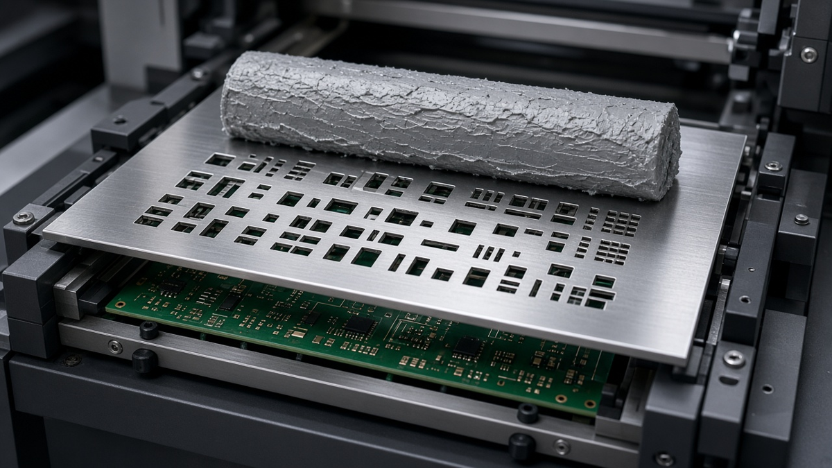
The paste Gerber is already frozen. The apertures are cut. The first article is scheduled. That is the moment most overseas buyers discover that stencil design and stencil print process are not the same problem. Bridging, starved deposits, smearing, and SPI scrap after the design is locked almost never get fixed by another aperture markup—they get fixed (or not) by frame choice, foil thickness compromise, printer settings, board support, SPI feedback rules, and how the stencil is cleaned and reused between lots.
This article is written for the assembly buyer and the process engineer who inherit a paste layer they can no longer rewrite. Aperture sizing, area-ratio math, windowpane patterns, and the stencil order table belong in our companion guide on SMT stencil aperture design by package and order spec. Here the question is different: once that companion work is done—or once a customer insists the paste file must be cut as-supplied—what process decisions still move first-pass yield on the SMT PCB assembly line?
What a frozen paste layer still leaves undecided
A locked paste Gerber answers only one question: where metal is open and where it is not. It does not answer the questions that decide whether those openings print the same on board 1 and board 400:
- Which printer frame size and tensioning method will hold the foil for this panel.
- Whether one foil thickness can serve the mixed package set, or a step stencil is required—and whether the layout even has room for the step transition.
- How the board will be supported under the print stroke so it does not flex away from the foil.
- What squeegee pressure, print speed, and separation speed the product will run under as its process window.
- Whether SPI rejects are wash-and-reprint, or "operator judgement," and who owns the trend data.
- How often the underside is wiped, how the stencil is cleaned offline, and when a foil is retired rather than reused.
None of those items appear as flashes in a Gerber. They appear as line items on the assembly work order, the printer recipe, and the traveler. If they are left to tribal knowledge, the same paste design can pass a first article and then drift through a production week as paste ages, the foil loads with residue, or a different operator changes support pins.
Treat the frozen paste layer as a fixed geometry. Treat everything below as process control that still belongs in the RFQ and the first-article release.
Framed, frameless, or step: choose for the printer you will actually run
Type selection is not a catalog preference. It is a match between foil, frame hardware, and the printer already booked for the job.
Framed foils for repeatable automated runs
A framed stencil bonds the stainless foil into a mesh-tensioned metal frame sized for a specific printer. Once mounted, tension is stable and the foil stays flat relative to the frame datum. That stability matters when the same panel runs day after day: alignment offsets stay small, snap-off distance stays consistent, and operators are less likely to introduce installation variation between shifts.
What the buyer should lock in writing:
- Exact frame outer dimensions that fit the printer on the booked line (not "standard frame").
- Foil orientation relative to the panel (which edge is the squeegee start).
- Whether the frame is dedicated to this revision or shared across similar boards—shared frames create mix-up risk if marking is weak.
- Storage: framed tools take space; bent frames print poorly long before apertures look worn.
Framed tools earn their keep when you expect multiple lots, stable panelization, and automated printing. They are the wrong default for a one-shot prototype if the factory must buy a frame size it will not reuse.
Frameless foils for high-mix and short runs
A frameless foil is a sheet that clamps into a reusable tensioning system at print time. Several products can share one tensioner, which cuts storage and frame inventory. For high-mix prototype and NPI work, that is often the honest choice.
The failure modes are different from framed tools:
- Tension depends on how the foil is seated. Uneven clamp pressure shows up as local print height variation that looks like an aperture problem.
- Operators who skip the seating checklist create board-to-board offset that SPI will catch as systematic X/Y shift on one zone of the panel.
- Foil edges are easier to ding in storage; a crease near a fine-pitch array ruins release even if the aperture cut is perfect.
RFQ callouts for frameless work: name the tensioning system class the factory will use, require a seating checklist on the traveler for first article and after any foil change, and demand stencil ID marking that ties foil, board revision, and panel drawing together. Do not accept "frameless, we will figure it out" when fine-pitch or BGA parts are on the board.
Step stencils when one thickness cannot serve both ends of the BOM
A step-up region thickens foil locally for connectors, shield cans, pin-in-paste leads, or power pads that need more volume. A step-down region thins foil around fine-pitch QFP leads, miniature passives, or tight BGA pads that would bridge or fail release at the board-wide thickness.
Steps solve real volume conflicts—but they constrain the printer, not just the laser cutter:
- The squeegee must climb or drop across the step. A keep-out band is required between the step edge and the nearest apertures on both sides. Dense layouts often have no room.
- Step on the contact (board) side versus the squeegee side behaves differently for gasket and paste roll. Confirm which the stencil maker can deliver for your panel.
- Local thickness changes change how the foil sits on warpage. A step near a bowed corner can open a gap that floods paste under the foil.
Before you order a step on a frozen paste design, ask layout (or accept the answer "no") whether the keep-out clears. If it does not, the remaining levers are aperture changes (back to the companion guide), selective dispense for a few high-volume joints, or accepting a thickness compromise and living with SPI scrap risk on one package family. Ordering a step that cannot physically print is wasted tooling.
| Choice | Buyer signal it fits | Process risk if mismatched |
|---|---|---|
| Framed | Stable panel, multi-lot, dedicated printer frame size | Wrong frame size; bent storage; unmarked shared frames |
| Frameless | High-mix, short run, shared tensioner | Seating variation; edge damage; weak foil ID |
| Step-up / step-down | Mixed paste volume that aperture tweaks cannot fix | Keep-out collision; squeegee transition; warp gap at step |
Thickness compromise when you will not reopen apertures
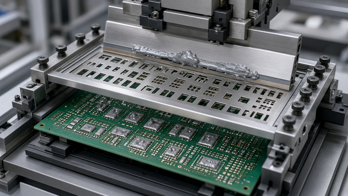
When the paste file is frozen and a step will not fit, thickness is the remaining global lever. Theoretical deposit volume scales with foil thickness for a given opening. That is physics, not preference. The buyer decision is which package family you are willing to protect and which you will manage with process margin.
Practical way to decide without rewriting apertures:
- List every unique aperture size class on the panel (fine passives, fine-pitch leads, QFN perimeter, BGA rounds, large connectors).
- Mark which classes already sit near release limits at the thickness you are considering (small openings in thick foil are the usual failure).
- Mark which classes need mechanical fillet strength or hole fill (connectors, pin-in-paste).
- Pick the thickness that keeps the smallest critical openings printable, then decide how you will compensate the large pads: accept more process scrap on those pads, add selective dispense, or reopen only those apertures—not the whole paste layer.
What not to do: pick a "middle" thickness because it feels fair to every package, then discover after SPI that fine apertures starve and large pads still bridge. A compromise without a named sacrifice package is not a process plan.
Document the choice on the traveler: foil thickness, why it was chosen, and which package family is the controlling constraint. When scrap appears later, that note stops the argument from restarting as "maybe the apertures are wrong" when the real issue is a thickness that was never matched to the frozen openings.
Printer settings that still move yield after geometry is locked
With foil type and thickness set, the printer recipe decides whether paste fills apertures, releases cleanly, and stays on the pads. Buyers rarely see these numbers on a quote, yet they dominate lot-to-lot drift.
Squeegee pressure and print speed
Too much pressure forces paste under the foil (smear, bridging after release) and can scoop paste out of large openings. Too little leaves fine apertures underfilled. Print speed interacts with paste rheology: fast strokes on a paste that has not returned to working viscosity after cold storage leave incomplete fills that look like aperture clogging on SPI.
RFQ / first-article ask: require the factory to record pressure, speed, and squeegee type/angle for the released recipe—not only "print OK." When a second lot drifts, you need those numbers to compare, not tribal memory.
Separation (snap-off) and contact
After the stroke, the foil separates from the board. Separation that is too fast pulls paste strings or leaves ragged peaks; separation that is too slow can smear if the gasket is poor. Some printers run near-zero snap-off (on-contact); others keep a small gap. The frozen paste design does not encode this. The product recipe must.
On fine-pitch and small BGA pads, separation quality shows up first as height variation and ragged deposit edges on SPI—before reflow ever opens a joint.
Paste condition on the stencil
Paste life on the foil during a long run is a process variable. Paste that dries in small apertures prints short deposits that look like design failures. Ask how the line manages paste kneading, replenishment, and maximum open time on the stencil for your paste type. If the factory cannot state a paste-handling rule for your alloy and powder size, SPI scrap on fine apertures is a scheduled event, not a surprise.
Board support: the silent cause of "random" zone failures
Uneven deposits clustered on one side of a panel, or along the long edges of a thin board, are often support problems dressed up as stencil problems. During the print stroke the board must not flex away from the foil. Soft spots under large BGAs or connectors create local gaps; paste either underfills or floods.
What good support looks like in practice:
- Support pins or blocks placed to the panel drawing, not to habit from the previous job.
- Vacuum tooling when the board and panel allow a seal—especially thin or large panels.
- Clearance for components already on the reverse side of a double-sided assembly (second-side print must not crush first-side parts).
- Rails and tooling holes that match the panel you are actually printing, including any last-minute panelization change.
Buyer callouts that prevent week-two scrap:
- Attach or approve a support map for first article on any board thinner than the line's comfort zone, any large panel, or any second-side print over tall parts.
- Require that SPI zone failures trigger a support check before anyone orders a new stencil.
- Freeze panel drawing and tooling holes before the foil is cut; a panel change after cut scrapes both stencil and support setup.
Warpage compounds support. Boards that leave fab bowed will never gasket evenly. Incoming flatness checks belong in the same conversation as print yield—otherwise the printer is asked to compensate for a fabrication problem it cannot fix.
SPI as closed-loop process control, not a pass stamp
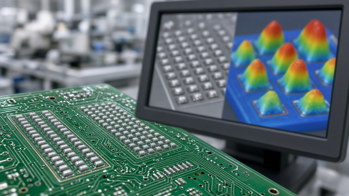
Solder paste inspection after the printer measures volume, height, area, and offset per deposit. Used well, it is the only gate that can catch print defects before placement and reflow make them expensive. Used poorly, it becomes a green checkmark that nobody trends.
What SPI can and cannot prove
SPI can prove that paste volume and position match the window set for this product before parts go down. It cannot prove the joint will survive reflow, and it says nothing about component coplanarity or placement. Do not treat SPI pass as assembly pass.
Defect patterns that point back to process, not paste Gerber
| SPI / print symptom | Likely process cause when paste is frozen | First check |
|---|---|---|
| Systematic offset across whole panel | Fiducial recipe, foil seating, frame registration | Vision recipe and frameless seating |
| Low volume on one aperture family only | Clogged openings, dried paste, local release issue | Underside wipe, paste age, aperture cleanliness |
| Low volume in one board zone | Support / flex / warp gap | Support map and board flatness |
| Bridging / excess height near large pads | Pressure too high, poor gasket, thick foil for that zone | Pressure, support, step/thickness decision |
| Ragged peaks / strings | Separation too aggressive or paste rheology off | Separation speed, paste conditioning |
| Progressive drift over a shift | Underside residue build-up, paste drying, squeegee wear | Wipe interval, paste open time, squeegee inspect |
Buyer rules that make SPI useful
Write these into the work order, not into a hallway conversation:
- SPI is mandatory for the product classes you care about (fine-pitch, BGA, QFN, miniature passives)—not "available."
- Failures are wash-and-reprint by default until a named engineer releases an override. "Operator judgement" without a rule creates silent escapes.
- Trend review exists: repeated fails on the same aperture group stop the lot and force a process action (clean, support, pressure, paste) before more boards print.
- First-article SPI data is retained and available for your review on request for the lot.
If the factory cannot describe the closed loop—measure, stop, correct printer, reprint—you are buying inspection theater. The frozen paste file will take the blame for problems the printer created.
For broader placement of SPI among other gates on the line, see our testing and inspection overview; this section is only about using SPI to control the print process itself.
Cleaning, coating wear, and when reuse becomes a yield risk
A stencil that printed well on Monday can smear on Thursday because the underside is loaded with paste. Cleaning is process control, not housekeeping.
Underwipe during the run
Printers wipe the foil underside on a set interval. Too rare, and residue bridges fine openings. Too frequent with an aggressive solvent, and you disturb paste in apertures or wear a release coating. The interval should be product-specific for fine-pitch work, not a line default copied from a coarse board.
Ask for the wipe interval and solvent class used on your first article, and require the same on production unless a process change is signed.
Offline clean between lots
After a lot, paste must leave the apertures, not only the surfaces. Incomplete clean leaves hardened plugs that print as intermittent shorts or opens—the worst SPI signature, because it comes and goes. Cleaning chemistry must match the paste; the wrong cleaner leaves a film that hurts release on the next run.
Nano-coatings and wear
Release coatings reduce paste sticking to walls and can widen the process window on marginal openings. They wear. A coated foil that has been through many cleans will not behave like the first article. If your fine apertures depended on the coating for release, treat coating life as a consumable limit: track print cycles or clean cycles, and retire or re-coat before SPI scrap climbs.
Reuse criteria (write them down)
Reuse the foil only when all of the following still hold:
- Same board revision and same panel drawing (including rails and fiducials).
- Foil flat, unkinked, unmarked by dents near active apertures.
- Apertures clear under magnification for the finest openings on the board.
- Frame undamaged (framed) or edges undamaged (frameless).
- Coating status known if coating was part of the release margin.
- Stencil ID still matches the traveler.
If the panelization changed, the paste revision changed, or fine apertures show wear, cut a new foil. Reusing a stencil into a new panel layout is a classic source of "mysterious" misalignment that wastes a production day.
Double-sided print and second-pass constraints
On double-sided SMT, the second print happens over a board that already carries parts on the first side. Support must clear those parts. Paste and heat history on the first side constrain how aggressively you can wash a misprint on the second side. SPI on the second side still matters—hidden joints on the second-side BGA will not forgive a bad print just because the first side looked fine.
Call out on the order: print sequence (which side first), maximum part height under the second-side support plan, and whether a second-side misprint is washable or scrap. Those decisions are process choices, not Gerber attributes.
First-article print release: what to freeze before volume
A useful first-article print release is a short package, not a verbal "looks good":
- Confirmed foil type (framed / frameless / step), thickness, and stencil ID tied to board and panel revision.
- Printer recipe: pressure, speed, separation, snap-off/contact mode, squeegee type.
- Support map for the panel, including second-side clearances if applicable.
- Paste type, powder size, and open-time / replenishment rule used.
- SPI window definition and sample of first-article SPI results for critical aperture classes.
- Wipe interval and offline clean method.
- Named package family that drove thickness or step choice (the controlling constraint).
- Explicit statement that paste Gerber modifications are out of scope for this release—or, if any last-minute aperture edit was made, a pointer back to the aperture companion process and a revised stencil ID.
Without that package, volume production inherits hope. With it, when yield moves you can tell whether the foil, the printer, the support, or the paste handling changed.
RFQ and PO callouts for print process control
Use this as a checklist when the paste layer is already decided and you are buying assembly, not redesign:
| Callout | Why it belongs on the PO / traveler |
|---|---|
| Paste Gerber revision + "cut as supplied" or "assembler may modify per report" | Prevents silent double-editing or zero-editing |
| Panel drawing revision and fiducial scheme | Stencil and support follow the panel, not the single board |
| Framed vs frameless; frame size or tensioner class | Matches real printer hardware |
| Foil thickness; step map and keep-out confirmation if stepped | Locks volume strategy |
| Printer recipe to be recorded at FA | Makes drift diagnosable |
| Support map required for thin / large / second-side boards | Prevents zone scrap |
| SPI mandatory; wash-reprint rule; data retention | Closes the loop |
| Wipe interval + offline clean method | Protects fine apertures across the lot |
| Stencil reuse rules and retirement triggers | Stops worn foils from entering a new lot |
| Print side sequence for double-sided | Protects first-side parts and wash decisions |
If a quote is silent on these items, the factory is quoting a cut foil and a print stroke—not a controlled process. Price comparisons that ignore the rows above compare different things.
What to decide before you release the next lot
You do not need another aperture tutorial to raise print yield on a frozen paste design. You need a short, written process plan. Before the next lot leaves the printer, decide and record:
- Frame path: framed for stable multi-lot work on a known frame size, or frameless with a seating checklist for high-mix—never an unnamed default.
- Thickness or step: which package family is the controlling constraint; whether step keep-out fits; what you will sacrifice if you compromise.
- Support: is there an approved support map for this panel and side, especially if the board is thin, large, warped-risk, or second-side?
- SPI rule: wash-and-reprint by default, trend stop on repeated aperture-family fails, FA data retained.
- Clean / reuse: wipe interval, offline clean method, and hard criteria for retiring the foil before the next revision or panel change.
Walk that list against the traveler you have today. Any blank line is a place scrap can hide while everyone argues about the paste Gerber. Fill the blanks first; reopen apertures only when the process plan says geometry—not printer control—is still the limiting factor.