
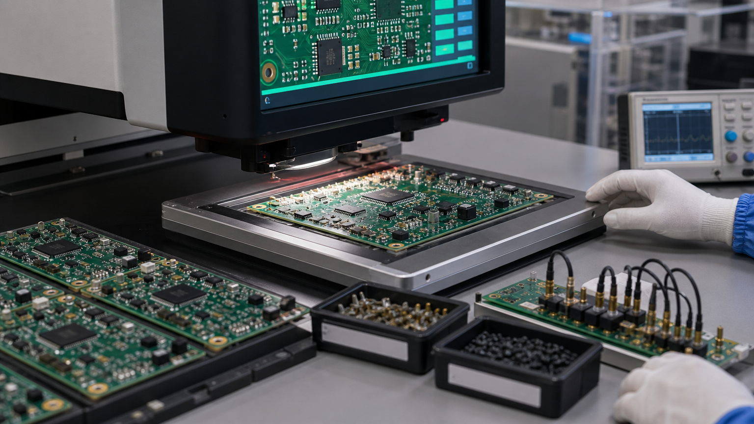
Unmarked 0402 resistors make the BOM the only source of truth on the line. Yet many articles stop after decoding 103 as 10 kohm. Overseas PCBA work needs the next layer: which film technology you bought, whether the imperial size matches the footprint, and whether the copper under that 0603 can actually dump the heat your continuous wattage assumption assumed.
Chip resistors look trivial until a reel mix-up, a metric/imperial footprint collision, or a sulfur-driven open on a field return turns them into the most expensive "cheap" part on the board. This guide is written for buyers and NPI engineers who must read markings when they exist, trust process control when they do not, and write fab/assembly notes that survive a China SMT line.
What "chip resistor" actually means on a modern reel
In purchasing language, chip resistor usually means a rectangular SMD resistor. In process language, you still need the package family and film technology, because nozzle selection, AOI models, and pulse behavior are not interchangeable.
Rectangular thick-film chips dominate consumer, industrial control, and many automotive body-electronics boards. The ceramic body is typically 96% alumina. Ruthenium-oxide (or related) paste is printed, fired, laser-trimmed, glass-passivated, and terminated. The process is mature, cost-effective, and good enough for the majority of digital pull-ups, LED current sets, and general analog dividers.
Thin-film chips serve precision and low-TCR needs: measurement front ends, reference dividers, and circuits where +/-1% is not enough or where temperature drift must stay tight across the operating range. Expect higher unit price and sometimes longer lead times on odd values.
MELF (Metal Electrode Leadless Face) parts are cylindrical. They appear where pulse handling, stability, or legacy automotive/industrial footprints demand them. They need different placement nozzles and AOI libraries than flat chips. If your assembler has never run MELF on that line, treat first-article risk as real, not theoretical.
Imperial vs metric size codes (stop mixing them in one drawing note)
Designators like 0603 (imperial) correspond to metric 1608 (1.6 mm x 0.8 mm). The first pair of digits is length; the second is width. A 1206 imperial part is about 3.2 mm x 1.6 mm and is often written 3216 in metric catalogs.
Mixing a metric drawing callout with an imperial ECAD library footprint is a classic China NPI delay: the CAM/assembly team builds to the Gerber land pattern while purchasing buys the metric-labeled reel that matches the BOM text but not the copper. Someone eventually notices after stencil design or after first-article AOI.
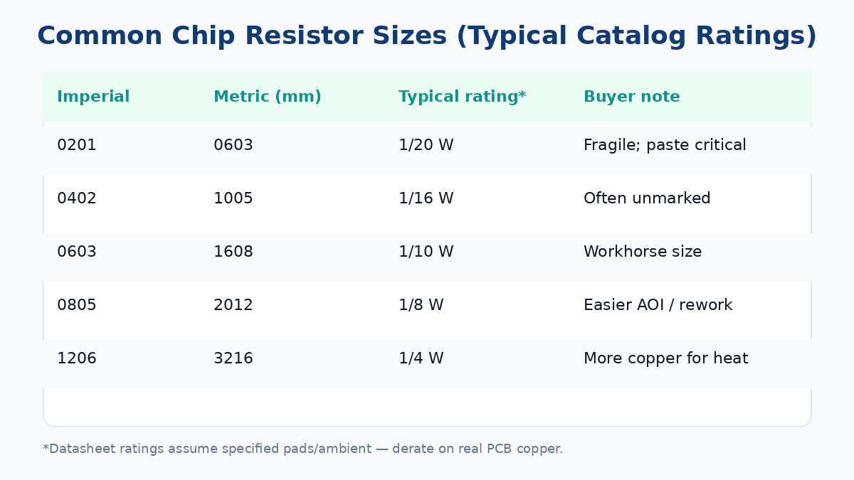
A practical size ladder buyers still see every week:
| Imperial | Approx. metric | Typical catalog power* | Buyer note |
|---|---|---|---|
| 0201 | 0603 | 1/20 W | Fragile; paste and tombstoning dominate yield |
| 0402 | 1005 | 1/16 W | Often unmarked; reel discipline is everything |
| 0603 | 1608 | 1/10 W | Common workhorse for mixed digital boards |
| 0805 | 2012 | 1/8 W | Easier rework and AOI than 0402 |
| 1206 | 3216 | 1/4 W | More body area for heat and marking |
\*Datasheet ratings assume specified pad copper and ambient conditions. They are not infinite ground pours you forgot to draw.
Miniaturization pressure pushed many consumer designs from 0805/0603 into 0402/0201. That is fine when the assembler qualifies the process. It is not fine when a power-dissipating sense resistor silently "fits" in 0402 on the schematic symbol but cooks the board in the enclosure.
How to read SMD resistor codes when the body is marked
Resistance values follow E-series preferences (E24 for many general-purpose parts, E96 for many 1% families). Marking systems are not mystical once you separate three cases: 3-digit, 4-digit, and R-as-decimal.
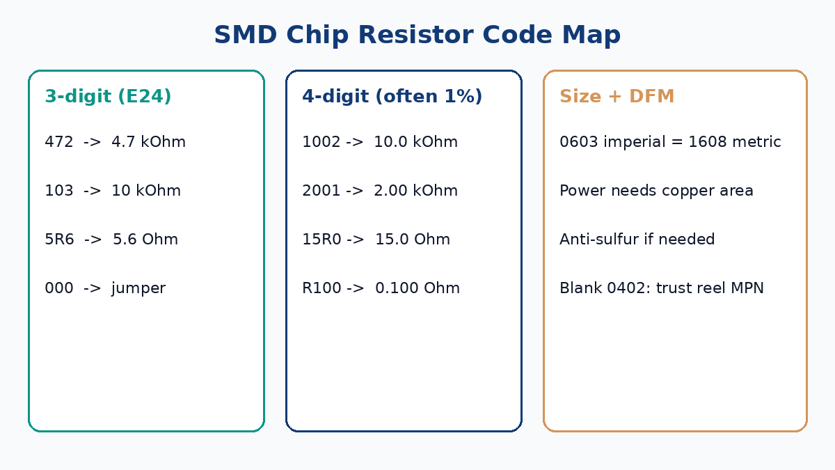
3-digit codes (common on larger E24 parts): first two digits are significant figures; the third is the decade multiplier (number of zeros). Examples:
472= 47 x 10^2 = 4.7 kohm103= 10 x 10^3 = 10 kohm114= 11 x 10^4 = 110 kohm5R6= 5.6 ohmR39= 0.39 ohm000or0R0= jumper (still confirm current rating)
4-digit codes (often 1%): first three digits are significant figures; the fourth is the multiplier. Examples:
1002= 100 x 10^2 = 10.0 kohm2001= 200 x 10^1 = 2.00 kohm15R0= 15.0 ohm4R80= 4.80 ohm
MELF color bands reuse through-hole color-code logic (3-, 4-, or 5-band). Verify against the reel label; do not invent band readings under poor lighting on a busy line.
Anything 0603 and smaller may be blank. Process control beats magnifiers. The reel label, bag label, and feeder setup record are the marking.
Terminal stacks and why "cheap odd-lot" parts fail in reflow
Chip resistor terminations are usually a three-layer system: an inner electrode (often silver-bearing), a nickel barrier, and an outer tin (or other solderable) finish. The nickel barrier exists so reflow solder does not dissolve the silver-bearing inner electrode and lift the end cap.
Cheap gray-market or poorly specified odd-lot parts without a proper barrier are a reliability gamble. Lead-free soldering and multiple reflow passes make that gamble worse. Stick to named manufacturer part numbers (MPNs) on the BOM. "Equivalent 10k 0603" is not a purchasing specification when the board must pass field life.
RoHS-era outer plating is typically lead-free tin systems. That is normal. What is not normal is skipping MPN control and hoping the distributor's "house brand" matches your qualification sample from last year.
Power, copper, and the failure case buyers actually see
Underrating dissipation is a leading cause of resistor damage during operation (and sometimes during aggressive rework heat). Catalog 1/10 W on 0603 assumes datasheet pads and airflow. A tall plastic enclosure, still air, solder-mask-defined pads with minimal copper, and a nearby hot regulator change the story.
Concrete buyer habit: for any resistor that dissipates more than a trivial fraction of its rating in continuous use, ask layout to show copper area and thermal relief intentionally. Sense resistors and LED strings are frequent offenders. If the design needs 0.5 W continuous, do not "save space" with a part whose body cannot reject heat on that land pattern—step up package size or use a dedicated power resistor family.
Pulse and surge are separate from continuous wattage. Thick-film chips, thin-film chips, and MELF parts do not share the same pulse curves. If your load is inductive kick, capacitive inrush, or short overload, pull the pulse graph from the datasheet—do not average it into DC watts.
Sulfur, humidity, and environment callouts that belong on the BOM
Sulfur-rich environments (some paper-mill, rubber, polluted warehouse, or under-hood automotive contexts) can attack silver-bearing terminations over time and open the resistor. Anti-sulfur resistor families exist specifically for this. If your end product ships into those environments, anti-sulfur must be an explicit BOM attribute, not a tribal memory in one engineer's head.
Humidity and cleaning chemistry also matter for precision thin-film parts after wash. If the assembler uses aqueous cleaning, confirm the resistor family's moisture and coating assumptions. "It worked on the prototype built by hand without wash" is not a process transfer.
BOM and DFM mistakes that repeatedly delay China PCBA
Pad geometry must match the library. Elongated pads and asymmetric copper invite tombstoning on small chips because one end reaches liquidus and surface tension wins. Uneven stencil apertures create the same failure mode.
Zero-ohm jumpers carry current. Treat them as links with an Imax and a package size that matches that current, not mystical shorts. A 0201 jumper across a power rail is a fuse you did not intend to design.
Do not let "value-only" BOM lines survive into production: R23, 10k, 0603 without tolerance, TCR, MPN, and manufacturer invites substitutions that break divider accuracy or pulse rating. Prefer full MPN plus approved alternates list.
When multiple values share one package on a dense board, feeder setup errors happen. Color-coding bags does not replace scan/verify discipline. Ask the assembler how they prevent similar-looking reels from swapping on dual-lane jobs.
For power-dissipating networks, derate by board copper and enclosure temperature. For precision networks, lock tolerance and TCR, and avoid mixing thick-film and thin-film randomly inside one matched divider.

A practical verification sequence before you release the files
- Decode any body marking only as a sanity check against the reel and BOM.
- Confirm imperial/metric size language is consistent across schematic, footprint, and AVL.
- Confirm datasheet power and pulse against real copper and ambient—not catalog optimism.
- Call out anti-sulfur, high-pulse, or high-reliability families explicitly where the environment demands them.
- Make sure assembly notes list non-standard packages (MELF) and any no-clean vs wash constraint that affects the passives.
Decode the marking to verify the reel. Use the datasheet and copper to verify the design. Only then is the chip resistor actually specified.
When package families and land patterns get messy across the whole board, XFPCB support can review resistor MPNs and size codes with your Gerbers during quote. Request a quote with the BOM and assembly notes attached so feeder and DFM risks are visible before stencil cutting—not after first-article scrap.