
The schematic was green. ERC reported clean. The layout DRC passed with the fab's minimums loaded. On first power the 3.3 V rail collapsed, the current limit on the bench supply tripped, and a regulator that had looked correct on paper sat hot enough to smell. That sequence is familiar to engineers whose breadboard "worked" and who still fear the first fab spin: software proved connectivity and clearance, not that the copper, stackup, and solder joints would behave as intended under load.
A schematic is a connectivity contract. A fabricated PCB is the first place that contract meets real parasitics, real assembly, and real mechanical fit. This article is for NPI and hardware teams who need to know what a China prototype build actually proves versus what ERC and LVS already covered -- and how to write an RFQ so the first spin teaches something useful instead of only confirming that copper exists.
What software checks catch before copper exists
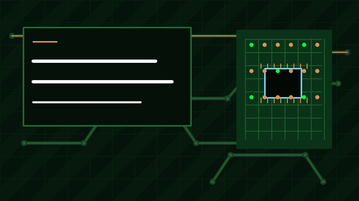
Electrical Rules Check (ERC) is the first gate that belongs before any Gerber leaves the building. A well-configured ERC matrix flags floating inputs, conflicting drivers on one net, missing power pins, and polarity mistakes that would become hard shorts the moment the board sees voltage. Footprint and pin-mapping review sits next to ERC: a symbol that looks right can still map pin 1 to the wrong land pattern, and that error survives every clearance check until silicon or a polarized capacitor is soldered the wrong way.
Layout Design Rule Check (DRC) then enforces the geometry you told the tool to care about -- trace width, spacing, via size, copper-to-edge, and often impedance constraints if you entered them. Design for manufacturability review goes further than a green DRC: fab CAM looks for acid traps, slivers, mask dams that cannot be resolved, annular ring after drill tolerance, and aspect ratios that will not plate cleanly. Those gates reduce the chance that the first spin arrives with opens, bridges, or undrillable features.
Netlist comparison and LVS-style checks close the digital loop by confirming that copper nets still match the schematic after routing. When those checks are honest and the libraries are trusted, many catastrophic "dead short on first power" failures never reach the fab. What they do not prove is whether the design works as a product under real parasitics, real current, and real packaging.
What only a physical PCB reveals
Once boards exist, variables that CAD treated as ideal show up as measurement. Signal integrity under real edge rates and return paths is different from a schematic wire with zero length. Power distribution that looked stiff in a DC IR drop plot can droop, ring, or oscillate when bulk and ceramic capacitors meet plane inductance and connector resistance. Thermal maps under sustained load expose copper and via arrays that were never stressed in simulation, or heat sinks that collide with mechanical keep-outs you only discover when the enclosure is closed.
Mechanical fit is its own test. Connector positions, mounting holes, stiffener height, and cable bend radius either clear the housing or they do not. A breadboard never proved that. Assembly quality learning is equally physical: paste volume, tombstoning risk on unbalanced pads, BGA voiding, and rework access only appear after SMT. Early-issue discovery is the real economic argument for a small prototype lot -- a handful of boards that fail on the bench cost less than discovering the same fault after tooling a volume panel.
The fabricated board also validates schematic intent in a way symbols never can. Intent is not only "net A connects to net B." Intent is that the regulator starts cleanly into the intended load, that the reset supervisor trips at the voltage you claimed, that the high-speed link trains with the stackup you paid for, and that the board still works after vibration or thermal cycling if those are part of the product duty. Software checks protect connectivity and manufacturability. The prototype protects assumptions.
Design-for-test habits that make the first spin informative
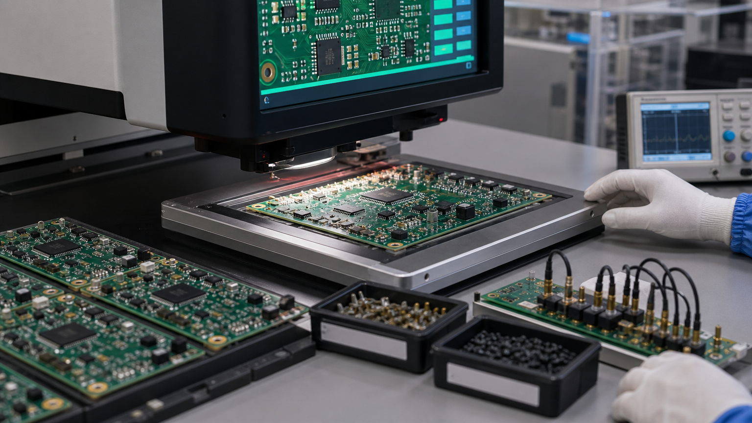
Bring-up goes faster when the artwork anticipates measurement. Accessible test points on rails, grounds, clocks, and critical control lines let a scope and meter answer questions without scraping soldermask. Zero-ohm links or FET switches on rails isolate domains so a collapsed 3.3 V net does not take the whole board down while you hunt the short. Current-limited first power -- often with a series resistor or a supply set below the expected draw -- turns a dead short into a survivable diagnostic instead of a charcoal pad.
Programming and debug headers that survive the enclosure, clear silkscreen for polarity and revision, and room for a temporary current shunt on a power entry path are the same idea in different clothes: leave a path for evidence. When the NPI plan calls for ICT or flying-probe later, pad access and net naming that match the schematic save fixture time. None of this replaces ERC. It makes the hours after the courier delivers the first panels productive, because every rail and interface you care about can be observed without inventing probes under a fine-pitch package.
Fab ET and AOI versus your functional plan
China fabs typically run automated optical inspection against the Gerber copper and electrical test (flying probe or fixture) for continuity and isolation on bare boards. Assembly lines add AOI on SMT, and often X-ray on bottom-terminated packages. Those gates answer a manufacturing question: does the delivered hardware match the files and process window? They do not answer whether your schematic's control loop is stable, whether firmware boots with the crystal you chose, or whether the PDN holds when all radios transmit at once.
Treat fab ET/AOI as a prerequisite, not a substitute. Your functional plan should name what "schematic intent passed" means: rail sequence and current budget, interface link training, sensor accuracy at temperature, mechanical fit in the intended housing, and any stress the product will see in the field. Log failures against nets and assumptions, not only against "board bad," so the next Gerber revision changes the right thing. A prototype lot that only confirms the fab can etch your copper is an expensive continuity coupon. A prototype lot that executes a written bring-up script is a validation tool.
Spin a purposeful prototype RFQ
When you send the job to XFPCB or another China fab for NPI, say what the spin is for. State layer count, material and Tg, finish, IPC class, and whether the lot is bare board or turnkey assembly. Attach Gerbers or ODB++, drill, fab notes, and -- when assembly is in scope -- BOM, centroids, and any AVL rules. Call out impedance coupons, controlled dielectrics, and mechanical keep-outs that the enclosure already proved sensitive. Ask for the ET and AOI coverage you expect on the traveler, and separate that from the functional tests your lab will run after delivery.
Quantity should match learning, not optimism: enough boards for destructive analysis, a mechanical fit unit, and a unit that stays under firmware while you iterate. Same materials as the intended production stackup matter when SI, thermal, or CAF risk is on the critical path; a substitute laminate that "is close enough" teaches the wrong lesson. Lead time language belongs next to file completeness -- CAM holds from missing stackup notes waste the same calendar that quick-turn pricing was meant to buy.
A green schematic is necessary. It is not proof. The first fabricated PCB is where schematic intent meets copper, solder, heat, and the box it must live in. Write the RFQ so that spin is designed to answer the questions software cannot, then power it with a plan that can survive the first wrong assumption.