
The quote lands like sticker shock: a full Rogers panel for a board where only the antenna feed and a short RF corridor need low-loss dielectric. Everything else is GPIO, power, and a modest MCU clock. The fab can build that all-Rogers stack. The buyer pays for it on every square centimeter, not just the RF strip.
That is the wrong way to hear "custom PCB material." Custom is not a brand name on a datasheet. It is a deliberate stack: core, prepreg, copper foil, finish, and thickness choices that match frequency, reflow, heat path, and lead time. Most boards do not need exotic laminate on every layer. They need the right gates applied early, then a stack the shop can press without inventing defaults.
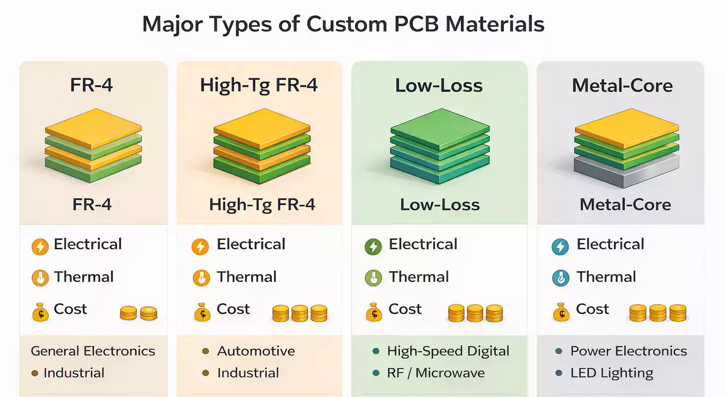
This article is written from a China fab quoting desk for buyers and engineers choosing FR-4, high-Tg, low-loss, metal-core, or hybrid builds. It sits beside our copper clad laminate notes on slash sheets and FR-4 class naming. Here the focus is the stack decision and when hybrid earns money versus whole-board Rogers or plain FR-4.
Custom material means the stack, not a logo
On the traveler, a "custom" material callout is a set of build decisions CAM can execute:
- Core family and Tg / Df class (or named grade when impedance locks to a datasheet Dk)
- Prepreg type and pressed thickness for each dielectric
- Copper foil weight and profile (standard ED, RTF, VLP/HVLP where loss budgets care)
- Overall thickness and layer count
- Surface finish that survives the reflow plan (HASL, ENIG, OSP, immersion tin/silver)
- Any metal base or thick copper for heat and current
Generic "FR-4, 1.6 mm, green" is a starting guess, not a custom selection. Custom means you already answered which of those dials are free and which are fixed by SI, thermal, or reliability.
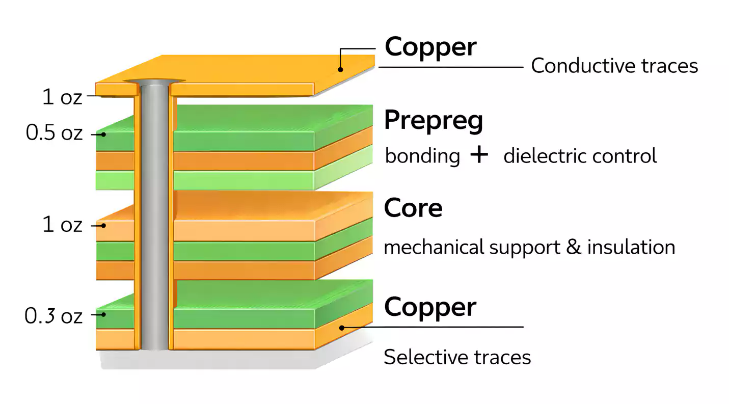
Cores are cured CCL. Prepreg is B-stage resin/glass that flows in press and sets dielectric height. Foil becomes outer (and sometimes inner) copper. Finish sits on exposed pads after etch and solder mask. Change any one without checking the others and impedance, peel, or press windows shift.
Three gates before you open a laminate catalog
Skip brand browsing until three gates are clear. Catalogs sell families; gates decide whether standard FR-4, high-Tg, low-loss, or metal-core even belong on the RFQ.
Gate 1 -- Frequency and loss
Ask where real RF or multi-gigabit energy travels, how long those routes are, and what insertion-loss budget the link can stand.
| Band / use | Typical posture | Why |
|---|---|---|
| DC to roughly 1 GHz, short digital | Standard or mid/high-Tg FR-4 | Df rarely dominates |
| Lead-free multilayer digital | High-Tg FR-4 class | Thermal survival more than Df |
| Multi-Gbps SerDes, longer runs | Mid-loss to low-loss FR-4-family | Df and Dk stability matter |
| RF / microwave corridors | Low-loss hydrocarbon / PTFE / ceramic-filled | Ultra-low Df, stable Dk |
| mmWave patches / radar | Specialty RF grades | Whole-board Rogers often still overkill if digital is separate |
Match material to the nets that carry the frequency, not to the highest clock printed on the MCU datasheet. A 2.4 GHz antenna feed on 30 mm of microstrip is a different problem from a full digital backplane at 25 Gbps.
Gate 2 -- Thermal: reflow, Tg, CTE
Lead-free SAC reflow peaks near 245-260 C. Resin softens above Tg; Z-axis CTE jumps and via barrels take the stress. For boards that see multiple presses, assembly reflows, and possible repair:
- Treat Tg around 170 C and up as a practical floor for lead-free multilayer work
- Prefer ~180 C class when layer count, BGA density, or automotive-style cycling is real
- Watch Td / T260 margin on thick stacks; "high Tg" wording alone does not guarantee delamination time
- Align Z-CTE expectations with via aspect ratio and HDI plans
High-Tg FR-4 is often the correct step when the board fails thermally, not electrically. Jumping straight to Rogers because "we do lead-free" is a cost mistake.
Gate 3 -- Heat path and metal-core
When LEDs, power FETs, or motor drivers dump watts into a small footprint, dielectric loss is not the first dial. Thermal conductivity and the path from pad to chassis matter.
Metal-core (usually aluminum, sometimes copper base) earns its place when:
- Junction-to-ambient needs a short path through dielectric into a metal plate
- FR-4 copper pours and thermal vias cannot meet the temperature rise
- The circuit is mostly single-sided power/LED with limited multilayer RF needs
MCPCB and multilayer FR-4 are different product lines on the shop floor. Mixing "I want Rogers impedance and an aluminum base on the same six-layer RF digital board" without a clear construction sketch is how RFQs stall.
Hybrid stack discipline from the fab view
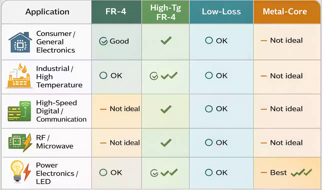
Hybrid is how many RF products should be built: low-loss on the layers that carry RF, economical high-Tg FR-4 elsewhere. Full-panel Rogers pays only when almost every dielectric in the stack must be low-loss, or when the board is small and RF-dominated.
What shops watch on hybrid RFQs:
Symmetry -- Press likes balanced copper and dielectric above and below the centerline. A thick Rogers core on one side and soft FR-4 on the other bows, registers badly, and invites scrap. Mirror critical dielectrics where you can.
Bondply / compatible prepreg -- Rogers-to-FR-4 interfaces need a bond ply or prepreg the fab has qualified for that pair. "Just use whatever FR-4 prepreg is on the shelf" is a delamination invitation. Name the bond system or ask the fab to propose one from stock.
Drill and desmear windows -- Ceramic-filled and PTFE-leaning materials wear bits differently and need different hole-wall prep than epoxy FR-4. Hybrid panels inherit the harder process for the specialty layers; quote time and drill cost rise even if only two layers are RF grade.
Dk / impedance ownership -- Impedance models must use the Dk of the dielectric the RF traces actually sit against, at the frequency that matters, with realistic pressed thickness. Swapping hybrid materials after layout without re-running the stack is a classic fail at impedance test.
When hybrid loses money -- Tiny boards that are almost all RF; very short schedule with no qualified bondply in house; or designs where RF routes snake across so many layers that "FR-4 everywhere else" no longer saves copper area or press time. Then a uniform low-loss stack can be cheaper in total landed cost.
When hybrid wins: antenna / PA / filter on outer or near-outer low-loss layers; digital, power, and connectors on FR-4; continuous RF ground discipline under the RF corridor; and a fab drawing that shows which layers are which family.
Prototype stock versus production stock
Prototype houses often stock a short list: mid/high-Tg FR-4, a couple of mid-loss options, maybe one Rogers-class sheet. Production may lock a named Isola / Shengyi / Rogers slash that matches the simulation library.
Moving from "whatever FR-4 the proto shop had" to a production-named low-loss grade without recalculating impedance is how first articles pass and volume lots fail. Prefer:
- Proto on the same family (or same Df/Dk class) you intend to buy at volume
- Or accept a controlled material change with a stackup rebuild and a coupon plan
- Confirm lead time for specialty sheets before promising a customer ship date--FR-4 is days; some PTFE and thin RF cores are weeks if not on the rack
Lead time is part of material selection. Over-spec that the fab must indent for is not "safer"; it is a schedule risk.
What belongs in the material RFQ
Close the loop in prose the quoting engineer can use. Put the operating frequency (or the nets that care), reflow / assembly temperature plan, and whether heat is a metal-core problem or a copper-pour problem. Attach a stack sketch that names core and prepreg families per dielectric, copper weights, and target thickness. If hybrid, mark RF layers, call out bondply expectations, and state impedance targets with the Dk frequency used in the model. Add finish, any CAF or automotive reliability notes, and whether prototype and production must share the same named grade.
That package lets a China fab propose FR-4, high-Tg, low-loss, metal-core, or a hybrid that pays for itself--without quoting a whole Rogers panel for a board that only needed a low-loss feed line.