
The display FPC passed schematic review with "EMI shield" stamped on the BOM line and still cracked after a few thousand hinge cycles. Camera cables that looked quiet on the first EMC scan lit up again after the laminated foil lifted near a stiffener edge. Another lot failed radiated limits because the printed shield never bonded into ground through the coverlay windows -- the paste looked continuous on the panel photo, but the return path was open. Schematic EMI intent is not the same as a flex cable that bends, sticks, and actually grounds.
Buyers and layout engineers who pick shielding by brochure name -- silver paste, carbon paste, aluminum foil -- often discover the failure later: bend life, delamination, or a controlled-impedance stack note that treated a decorative shield as a reference plane. This piece is factory-to-buyer language for FPC cables (display, camera, high-speed interconnects) from a China fab desk that quotes silver ink, carbon print, Al foil laminate, copper or hatch planes, and laminated EMI film on the same traveler family.
What flex cable shields must survive that rigid cans ignore
A metal can on a rigid board mostly has to cover, ground, and stay attached. A shield on a flexible cable has three extra jobs that dominate RFQ arguments:
Bend life. Dynamic hinges (laptop display, foldable camera arm, robotic wrist) see thousands to hundreds of thousands of flex cycles. Static folds that install once and sit still are a different traveler. The shield that survives a one-time form may still craze or peel when the cable is the hinge.
Adhesion. Printed pastes and laminated foils live on polyimide or coverlay. Moisture, flux residues, and mismatched lamination pressure show up as bubbles, edge lift, and delamination long before conductivity collapses in a multimeter check.
Thickness and stiffness. Every shield adds stack height. Minimum bend radius scales with total thickness, so a "stronger" shield can violate the mechanical envelope even when EMI attenuation looks excellent on a datasheet table. Rigid EMI solutions that ignore thickness are a poor template for FPC cables.
Those three constraints sit beside the usual EMI goals: keep external fields out of high-speed or analog pairs, keep the cable from radiating, and leave enough compliance for assembly into the product shell. If any one is missing from the RFQ, CAM will guess -- and guessing on flex shields is how cracked paste and open grounds ship.
Material menu with factory trade-offs
China flex lines commonly quote five shielding constructions. They are not interchangeable brochure synonyms.
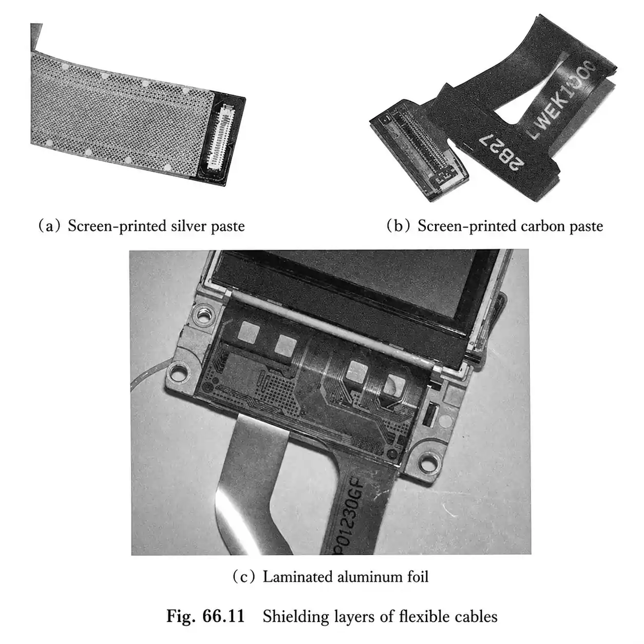
Screen-printed silver paste (silver ink). Conductive silver paste is printed over coverlay, cured, and often protected by an outer coverlay or film. Conductivity is strong for a printed film; selective print windows let you shield only the noisy segment of a long cable. Typical attenuation sits in a moderate band often cited around 20-40 dB depending on thickness, coverage, and frequency -- useful for many display and camera FPCs, not a guarantee at multi-GHz edges. Cost sits above carbon and below full copper-plane constructions. Silver paste still needs coverlay openings into ground copper so the ink can wet the pads; without those windows the shield is a floating conductor. Bend durability is usually good for moderate dynamic use, but thick prints and poorly cured layers still crack in tight hinge radii.
Screen-printed carbon paste. Same print process, much lower material cost, much higher sheet resistance. Carbon is a budget EMI coat for products that need a little quieting rather than a hard EMC margin. It is the wrong default for strict radiated limits, sensitive analog near switching rails, or high-speed differential that already sits near the compliance edge. Flexibility is generally fine; shielding effectiveness is the limiter.
Hot-laminated aluminum foil. Al foil laminated under heat and pressure forms a continuous metallic skin with strong shielding when grounded well. Reliability is high when lamination, adhesive, and bend-zone planning are matched. Failures we see in incoming analysis are rarely "aluminum is bad" -- they are foil across a dynamic bend without relief, foil under a stiffener transition with peel stress, or foil that was never bonded to ground copper. Plan shield zone versus bend zone early; Al foil hates being asked to be both hinge and Faraday skin in the same strip.
Copper layers (solid or cross-hatched) with stitching. Dedicated copper planes sandwiching signals remain the strongest electrical answer and the only common shield family that can also serve as a controlled-impedance reference when designed as such. Solid copper maximizes attenuation; hatch improves flexibility at some high-frequency penalty where apertures matter. The thickness and cost jump is real -- a copper-shielded flex can land as a multi-layer construction versus a single-circuit cable with a printed coat. Stitching vias that close the Faraday cage are stress risers in flex; IPC flex guidance discourages vias in the bend region for good mechanical reasons. Put stitch vias in stiffened or static zones, not in the hinge.
Laminated EMI shielding films. Composite films (insulation / thin metal / conductive adhesive) laminate onto coverlay and contact ground through selective openings, similar in grounding idea to silver ink but with a manufactured metal layer rather than a printed particle film. Thickness add is small compared with copper planes, flexibility is typically excellent for dynamic cables, and attenuation often sits between silver ink and copper-plane constructions depending on the film grade. Films are a frequent factory recommendation when bend cycle life and thin stack matter more than using the shield as an impedance reference. Like silver ink, they are not a substitute for a dedicated copper reference plane when you need controlled Z.
Coverlay openings and getting the shield to ground
Printed pastes and laminated films only become shields when they bond electrically into the board ground network. The usual factory method is selective coverlay openings (windows) over ground copper. Conductive paste or the film's conductive adhesive flows or presses into those openings and ties the outer shield to ground.
Window size, cleanliness, and registration matter. Windows that are too small or contaminated leave high-resistance or intermittent bonds that pass a soft continuity check and fail EMC after humidity or flex. Windows placed only at one end of a long cable can leave the far end poorly referenced at high frequency; multiple ground ties along the shield length are common when the cable is long relative to the wavelengths of concern.
Copper-plane shields ground through stitching vias rather than paste windows. That path is low impedance when via pitch is tight enough for the frequencies you care about -- and mechanically risky if those vias sit in the dynamic flex. Separate the electrical need (stitch density) from the mechanical keep-out (no vias in the bend) on the fab drawing so CAM does not "help" by flooding vias through the hinge.
Stiffeners complicate grounding and adhesion at once. A PI or FR-4 stiffener near a shield edge can create a peel step; a stiffener that covers the only ground window can block the conductive adhesive from ever seeing copper. Call out shield coverage, window locations, and stiffener outlines on the same mechanical drawing.
Impedance caveat: a shield is not automatically a reference plane
This is where brochure shielding and SI stack notes collide. Silver ink, carbon paste, aluminum foil skins, and many EMI films improve EMI containment. They do not automatically provide a stable, characterized return plane for controlled-impedance traces.
Printed particle films have higher and less uniform resistivity than copper foil. Film adhesives and process variation add impedance tolerance that SI calculators do not treat like a rolled or electrodeposited copper plane. If the channel needs 90 ohm differential or 50 ohm single-ended with a real tolerance, budget dedicated copper reference layers (solid or carefully specified hatch) in the stackup. You can still add a film or paste shield for extra EMI help, but do not delete the copper reference and hope the shield "counts."
Copper shield planes can serve as reference planes when stack spacing, copper weight, and hatch rules are part of the impedance model. That is a stackup decision, not a BOM afterthought. Tell the fab which layers are impedance references and which outer coats are EMI-only so CAM does not merge the intents.
Choosing by speed, bend cycles, and cost
Walk the decision in prose rather than a scoring chart. Start with mechanical class: static install-once fold versus dynamic hinge with a cycle target. Dynamic life pushes you toward thin films or well-qualified silver prints and away from solid copper across the bend; copper and Al foil belong in static spans or stiffened sections unless hatch and radius are proven.
Then overlay signal speed and EMC severity. Modest edge rates and soft EMI goals can live on carbon or light silver. Display and camera FPCs that already flirt with radiated limits usually need silver paste, EMI film, or Al foil with solid ground ties. Multi-gigabit or RF-ish flex that also needs controlled impedance needs copper reference planes in the stack -- optionally with a film shield for extra containment -- not paste pretending to be a plane.
Cost follows process steps and layer count. Carbon is cheapest and weakest. Silver paste and films add material and lamination or print steps without always adding a full copper layer. Copper-plane shielding is the premium electrical path and the thickest, stiffest option. Quote apples-to-apples: same shield zone map, same bend radius, same impedance notes. A cheap carbon quote that omits ground windows is not cheaper -- it is unfinished.
What to put on the flex EMI RFQ so CAM builds the cable you meant
Fabs quote what is drawn. Name the shield construction (silver paste, carbon paste, Al foil, copper/hatch, EMI film) and the zone it covers relative to the bend region and stiffeners. Mark coverlay ground windows or stitch-via keep-outs so grounding is intentional. State static versus dynamic bend, target radius, and any cycle life expectation that drove material choice. If controlled impedance is in play, list which copper layers are references and state plainly that outer paste or film is EMI-only. Call out stiffener conflicts with shield edges and windows. Attach the stackup sketch beside the mechanical drawing rather than burying shield intent in an email. XFPCB can confirm whether the printed, laminated, or copper-plane shield in that package is buildable on the flex construction before the cable becomes the hinge that cracks or the EMC failure that only shows up after tooling.