
“PCB mount” in product hardware means how the board attaches to a chassis—standoffs, screws, clips, rails—not keyboard switch folklore. Poor mounting cracks solder joints, violates creepage, and fights warpage. This article expands thin competitor notes into mechanical DFM for fab and assembly drawings: hole classes, keepouts, edge clearance, hardware callouts, and warpage versus chassis fit. No invented millimeter universal tables—freeze your numbers on the drawing.
Buyer decision frame: mechanical is part of the RFQ
Before fab, freeze:
- Mount scheme (standoff screw, clip, rail, adhesive)—primary and service access.
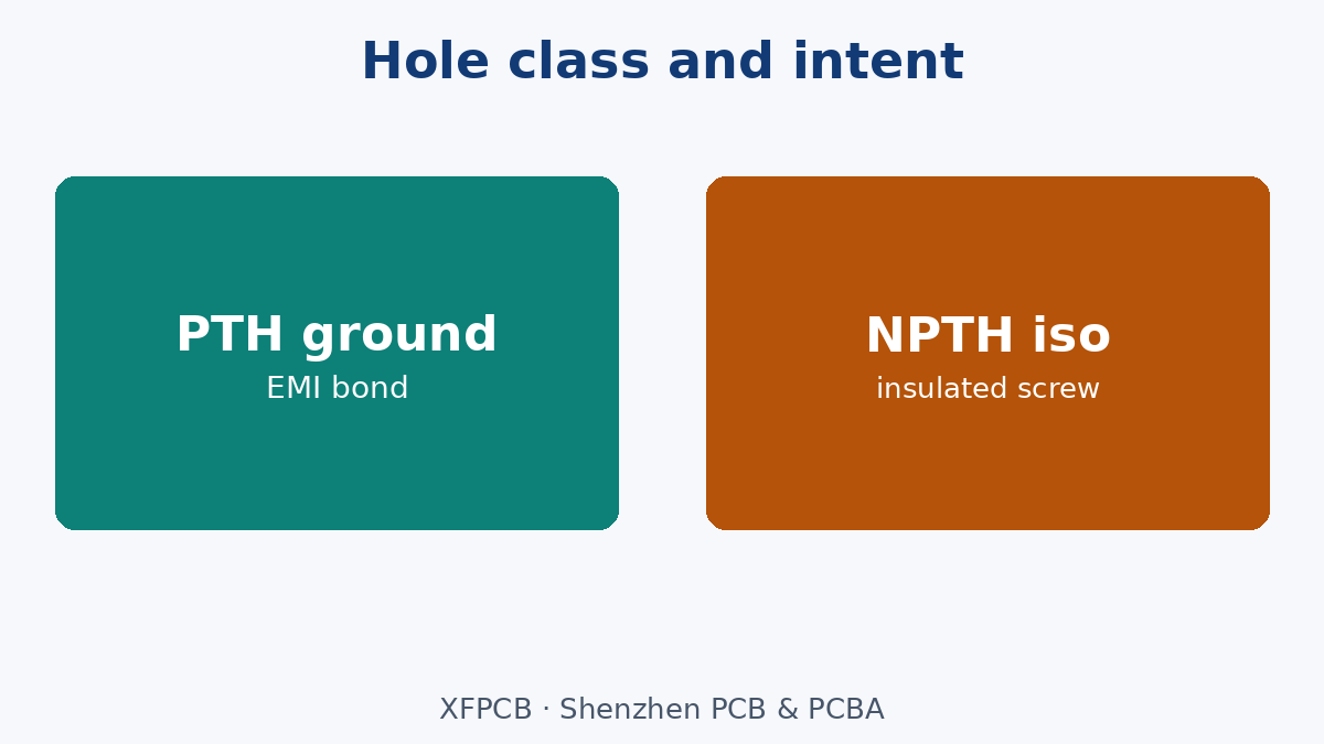
- Hole class per mount (PTH for ground, NPTH for insulated).
- Keepouts for copper, parts, and tall components near hardware.
- Chassis tolerance strategy (floating slots vs precision holes).
- Who owns hardware (BOM vs enclosure kit).
If mechanical is “later,” expect SMT joints to become hinges. See Manufacturing Files for drawing pack expectations and Industrial Control when vibration environments dominate—still put mounts on your drawing.
Standoffs and screws: what fab must see
Call out:
- Hole finished size and PTH vs NPTH.
- Annular ring and keep-out from traces.
- Whether metal standoffs intentionally ground to a plane.
- Insulating washers when screws pass near hazardous voltages.
- Torque notes belong to assembly, but pad mechanical strength is layout/fab.
Mismatched hardware vs hole class is a top assembly EQ. Align enclosure drawing and PCB hole chart.
Keepouts, edge clearance, and connectors
Mounting hardware needs copper/part keepouts so washers do not short and drivers fit. Board edge clearance for chassis walls and gaskets belongs on the mechanical drawing mirrored to PCB outline. Place heavy connectors near mounts so insertion force goes into the chassis, not into BGA corners mid-span. Cable strain relief is enclosure-owned but must match connector placement.
Warpage vs chassis fit
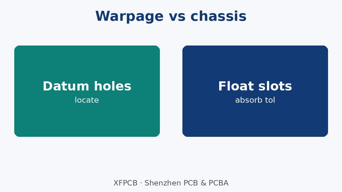
Boards that pass fab bow-twist may still rock on three standoffs if the chassis is non-planar or if reflow increased bow. Call flatness needs when heatsinks or connectors require coplanarity. Copper balance and stack symmetry (see stack document post) reduce warpage risk; mounting pattern that over-constrains a warped board cracks ceramics. Use slotted holes or controlled float when tolerance stacks demand it—document which holes are datum vs floating.
Clips, rails, adhesives
Clips speed assembly but fatigue; call engagement features and keepouts. Rails need guide geometry and end stops. Adhesives/potting reduce serviceability—name rework policy. Each scheme changes keepout and test access.
Failure modes
- Cracked joints at connector after vibration—mount too far.
- Intermittent ground—PTH mount intended to ground but mask tenting isolated it.
- Short to chassis—insufficient creepage to screw.
- Board bulge—four screws tightened on warped panel.
- Broken NPTH pads—screw pulled through soft laminate without proper pad/land design.
What fab/assembly can and cannot fix
Can: drill correct PTH/NPTH; hold outline tolerance; add keepout copper clears; assemble hardware per BOM.
Cannot: redesign chassis flatness; invent strain relief; make a mid-span BGA survive as a handle.
RFQ / drawing checklist
- Mount hole chart: size, PTH/NPTH, datum scheme.
- Keepouts for copper and components.
- Grounding intent for metal hardware.
- Edge clearance to chassis.
- Hardware on BOM or enclosure kit.
- Warpage/flatness notes if critical.
- Creepage notes near hazardous voltages.
- Assembly torque/sequence reference if required.
Common EQ loop
- PCB released without mechanical hole review.
- Enclosure arrives; holes misaligned.
- Slotted ECOs; connectors stress joints.
- Second spin adds mounts near connectors—should have been DFM round one.
Cost traps without invented prices
Extra mounts add hardware and drill cost but save warranty. Skipping mounts to save screws shifts cost to cracked BGAs. Over-precision hole positions without chassis capability burns yield. Align tolerance with the cheaper-to-fix side.
Stacked boards and mezzanines
Board-to-board standoffs need matched hole patterns and height that clear parts on both sides. Call max component height keepouts. Misaligned mezzanine mounts damage connectors during mate. Treat stacked mounts as a system drawing, not two independent PCBs.
Shipping and handling mounts
Some products ship with boards mounted; some mount at integration. If boards ship bare, specify packaging so mounting tabs and edges do not take impact. If partially mounted, torque and threadlocker policies belong in assembly docs. Fab cleanliness and mask dams near holes still matter for either path.
ESD and grounding mounts
Metal standoffs often form the ESD and EMI bond to chassis. If that bond is required, specify unmasked pads or selective mask opens and verify continuity in FCT. If isolation is required, specify NPTH plus insulating hardware—and prevent assemblers from “helpfully” using metal screws to chassis without washers. Mixed intent across holes is a common documentation failure.
Incoming inspection against method declarations
When first articles arrive, check that the traveler’s process stamps match the method statement: via types present on X-ray or microsection, line geometry consistent with subtractive vs SAP expectations, and lamination count if HDI sequential was claimed. Method fraud is rare; method mismatch from soft RFQs is common. Catch it at FAI, not after MP ramp.
Spare capacity and second-source method parity
If you dual-source, both plants must run the same method family and via architecture—or you must qualify differences. A second source that only offers through-via while the primary runs HDI is not a true alternate. Method parity belongs in the dual-source checklist beside material family parity.
Communicating method to assembly partners
Assemblers need to know if boards are thin HDI, heavy copper, or MCPCB because fixtures and profiles change. Pass the method one-pager to SMT with the board rev. Do not assume fab-to-assembly handoff includes process context—attach it.
Datum strategy for multi-board products
When several PCBs share one chassis, pick global datums so hole patterns do not fight. Document which board’s holes are primary datums. Use slotted holes on secondary boards to absorb tolerance. Enclosure drawings and PCB drawings must share the same datum story—exporting independent CAD models without a master is how misalignment lands in EQ.
Conformal coat and mount holes
If coating is in scope, define whether mount pads are masked. Coating under a grounding standoff kills the bond; coating in an NPTH may be irrelevant or messy. Put coat keepouts on the fab/assembly drawings with the mount chart.
Press-fit connectors and mounting interaction
Press-fit needs support during insertion—mounts and fixtures must take the force. Boards that rely on mid-span support only from a plastic clip may crack during press-fit. Coordinate press-fit process with mount locations before tooling.
Thermal interface hardware
Heatsinks screwed through the PCB need hole classes, insulation washers if required, and flatness. Torque sequences should avoid potato-chipping the board. Thermal hardware is mounting hardware—put it on the same mechanical DFM review.
Service mounts vs shipping mounts
Some screws exist only for shipping brackets and are removed in the field. Label them so service techs do not leave structural mounts missing. Conversely, do not expect shipping-only clips to survive life vibration.
Audit checklist for mechanical DFM release
Before Gerber release: hole chart reviewed against enclosure; keepouts reviewed against hardware OD; grounding intent reviewed with EMC owner; warpage risk reviewed with stack owner; connector proximity to mounts reviewed with packaging. Sign the checklist. Unsigned mechanical is unsigned reliability.
Plated mounting holes as EMI anchors
When mounts ground the board to chassis, treat them as intentional EMI bonds: short, multiple where needed, with copper that connects to the reference plane without skinny necks. Random screws into floating copper islands do not create a bond. Coordinate with the return-path / EMI layout discipline on high-speed boards.
Plastic enclosures and heat staking
Some consumer products heat-stake or ultrasonically stake plastic posts through NPTH holes. Call hole size for stake process and keepouts for melt flash. Stakes that over-constrain warped boards crack joints similarly to over-tight screws. Validate stake process on DFM builds.
Blind mounts and serviceability
Blind screw bosses behind batteries or displays make service destructive. If field service matters, place mounts for access or use captive hardware. Document service mounts in the maintenance manual—and ensure the PCB keepouts match the tool access you promised.
Vibration test correlation
If the product faces vibration quals, correlate mount spacing with expected mode shapes early. Adding mounts after failed vibe is expensive. Mechanical simulation is ideal; if unavailable, at least place mounts near heavy parts and connectors before EVT.
PCB thickness and screw engagement
Thin boards may need longer screws or threaded inserts in the chassis rather than relying on board thickness for thread engagement. Call insert use on the mechanical BOM. Screwing into FR-4 threads alone is usually wrong for repeated service.
Mask defined vs copper defined lands near mounts
Define whether mount pads are mask-defined and whether tenting covers nearby vias. Screws can abrade mask and expose copper—plan cosmetics and insulation accordingly. For grounding mounts, exposed copper is often required; for insulated mounts, mask and insulating washers cooperate.
Panel tabs near mount holes
Breakaway tabs placed too close to mount holes leave burrs or thin copper that tears at screw time. Keep panelization features away from mount lands per plant guidance. Include that keepout on the panel drawing.
Closing addendum
Mechanical DFM is complete when enclosure, PCB, hardware, and assembly torque tell one story. Until then, solder joints remain accidental structural parts—and that is a reliability defect waiting for vibration.
Mounting near batteries and coin cells
Retain clips and coin-cell holders stress boards if mounts are far away. Place mounts to support retention force. Insulation and keepouts around cell positives are mandatory—hardware shorts are painful failures.
Silk legends for mounts
Optional but useful: silk “GND” or “ISO” near mount holes matching intent, or assembly maps in the drawing pack. Silk is not a substitute for the hole chart—but it reduces assembly mistakes on dense boards.
Reciprocal keepouts on enclosure CAD
Export PCB keepouts back into enclosure CAD so mechanical engineers see screw head and driver clearances. One-way communication (enclosure to PCB only) misses packaging collisions. Close the loop before tooling soft jaws.
Ground braid and bonding straps
Some products add bonding straps from PCB mounts to chassis paint-free zones. Call strap attach points on both PCB and enclosure. Paint insulation is a classic EMI bond killer—mechanical DFM must include finish callouts on bond areas.
Robotics and automatic screwdriving
If assembly uses automatic screwdrivers, hole positional tolerance and boss strength must match robot capability. Float vs datum holes affect robot programming. Involve manufacturing engineering when volumes justify automation—do not discover misalignment after a screwdriver cell is tooled.
Final mechanical DFM gate
Hold a 30-minute gate with layout, mechanical, assembly, and EMC before tape-out. Walk the hole chart, keepouts, and connector mounts. Sign the gate form. Boards that skip this gate own their cracked joints.
Corrosion and hardware finish
In humid or industrial atmospheres, specify hardware plating and avoid dissimilar metal corrosion couples that shed debris onto the board. Stainless vs zinc vs aluminum choices belong in the mechanical BOM with environment in mind. Contaminated mount hardware becomes an electrical defect later.
Labeling mounts on assembly drawings
Number mount locations (MH1, MH2…) on both PCB and assembly drawings so torque sequences and inspection can refer to them. Unnumbered holes cause missed screws in audit. Consistency beats tribal knowledge on the line.
Spares and field replacement boards
Field replacement PCBs must match mount patterns of the chassis revision they enter. When enclosure ECOs move bosses, PCB revs must track. Maintain a compatibility matrix for service SKUs—mechanical DFM continues after first shipment.
Mount drawings without chassis revision references invite silent mismatches—always cite the enclosure drawing rev beside the PCB rev on the RFQ cover.
Closing: mechanical DFM is electrical reliability
Mounting is how solder joints avoid becoming structural members. Freeze hole classes, keepouts, grounding intent, and warpage strategy on fab and assembly drawings. XFPCB will drill and mask to those notes—bring chassis reality into the PCB RFQ early, and field vibration stops being a surprise.