
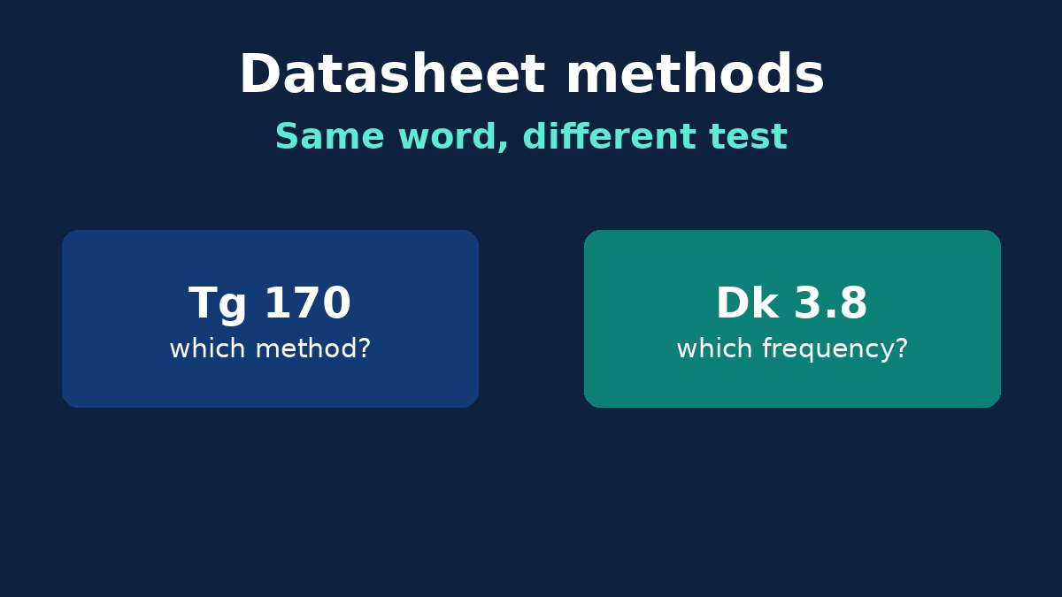
Two quotes can both say "high-Tg FR-4" and still not be offering the same material. The numbers on the datasheets are only comparable when they were measured the same way. Ranking a DSC glass transition against a TMA one, or a dielectric constant at 1 MHz against one at 10 GHz, is how a buyer "upgrades" into a laminate that is not an upgrade.
Which process the board is — a pressed laminate, a metal base, a ceramic substrate — is a separate decision. So is the buyer gate that picks a family in the first place. This note starts later: you are looking at two laminate sheets, and you need to know which rows you are allowed to subtract.
Tg is not one number
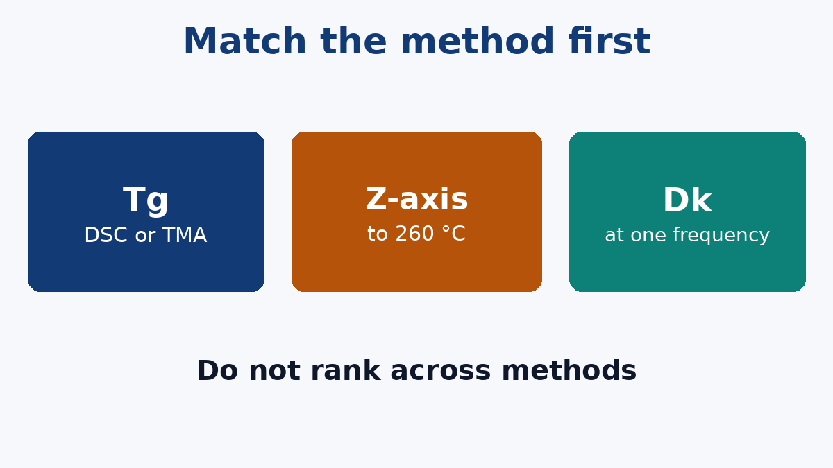
Glass transition is the temperature where the resin softens and the expansion rate jumps. Datasheets report it by DSC or by TMA, and those methods do not land on the same value for the same resin. DSC watches the heat flow. TMA watches the expansion. One sheet's 170 °C and another's 170 °C are the same claim only if both name the method.
A high-Tg callout is what you want when lead-free assembly or a hot environment is the reason you left standard epoxy. Our High Tg PCB page is that build, for lead-free and other higher-temperature jobs. The callout is still incomplete if one quote's Tg is DSC and the other's is TMA and nobody noticed. Ask both sheets for the same method before you treat the higher number as the safer board.
Tg is also not the decomposition temperature. A resin can have passed Tg by a wide margin and still be below the temperature where it starts to break down chemically. Lead-free reflow cares about both. Do not let a Tg win hide a weak Td, and do not let a Td win hide a Tg so low that the board is soft for most of the cycle.
Z-axis expansion is the row that cracks barrels
The expansion that stresses a plated through-hole is through the thickness, and it gets much larger once the resin is above Tg. Some datasheets quote a CTE in ppm per degree below Tg, where every decent laminate looks calm. Others quote the total percent expansion from 50 °C to 260 °C, which is the ride a lead-free profile actually takes.
Those are not interchangeable units. A low ppm number below Tg can still be a large percent to 260 °C. If the failure you are buying your way out of is a cracked barrel or a lifted pad after reflow or rework, compare the percent expansion over that hot range, on both sheets, not the room-temperature CTE. If a sheet only gives the below-Tg figure, it has not answered the question.
Dk and Df depend on the frequency you name
Dielectric constant and dissipation factor move with frequency, with resin content, and with how much of the copper's roughness the loss measurement includes. A Dk published at 1 MHz is a reasonable input for a slow board and a poor one for a multi-gigahertz pair. Averaging it with a 10 GHz number from the other vendor does not produce a third, truer Dk.
Our Impedance Control PCB page is the stackup and trace-geometry review against a target, checked with coupons. That review uses the Dk you supply. Hand it a number from the wrong frequency and the coupon will faithfully build the wrong impedance.
Loss is the same trap. A dissipation factor that looks fine at a megahertz does not say what a long channel will do. When the reason you are leaving standard epoxy is gigahertz loss, our High Frequency PCB page is the material and stackup review for that RF and high-speed work. Bring the Df at a stated frequency, from both candidates, or you are comparing slogans.
Three rows people mix up with the ones above
Water absorption. The number is only meaningful after a stated conditioning: how long, how hot, immersed or not. Moisture moves both Dk and insulation resistance. If one sheet is "as received" and the other is after a day in water, the drier-looking one has not won.
Tracking versus breakdown. Comparative tracking index, tested under IEC 60112, is about the surface forming a conductive path in the presence of contamination and moisture. It is not the voltage the dielectric will stand through its thickness. A high CTI does not answer a hi-pot question, and a hi-pot number does not answer a surface-creepage question. Name which failure you mean.
Copper foil. Roughness is a loss and an impedance term of its own. It is not a property of the resin. If one quote includes a low-profile foil and the other includes standard electrodeposited foil, you are no longer comparing laminates. Say the foil in the same sentence as the resin, or the Df comparison is doing two jobs at once.
Embedded foil is not a row on this sheet
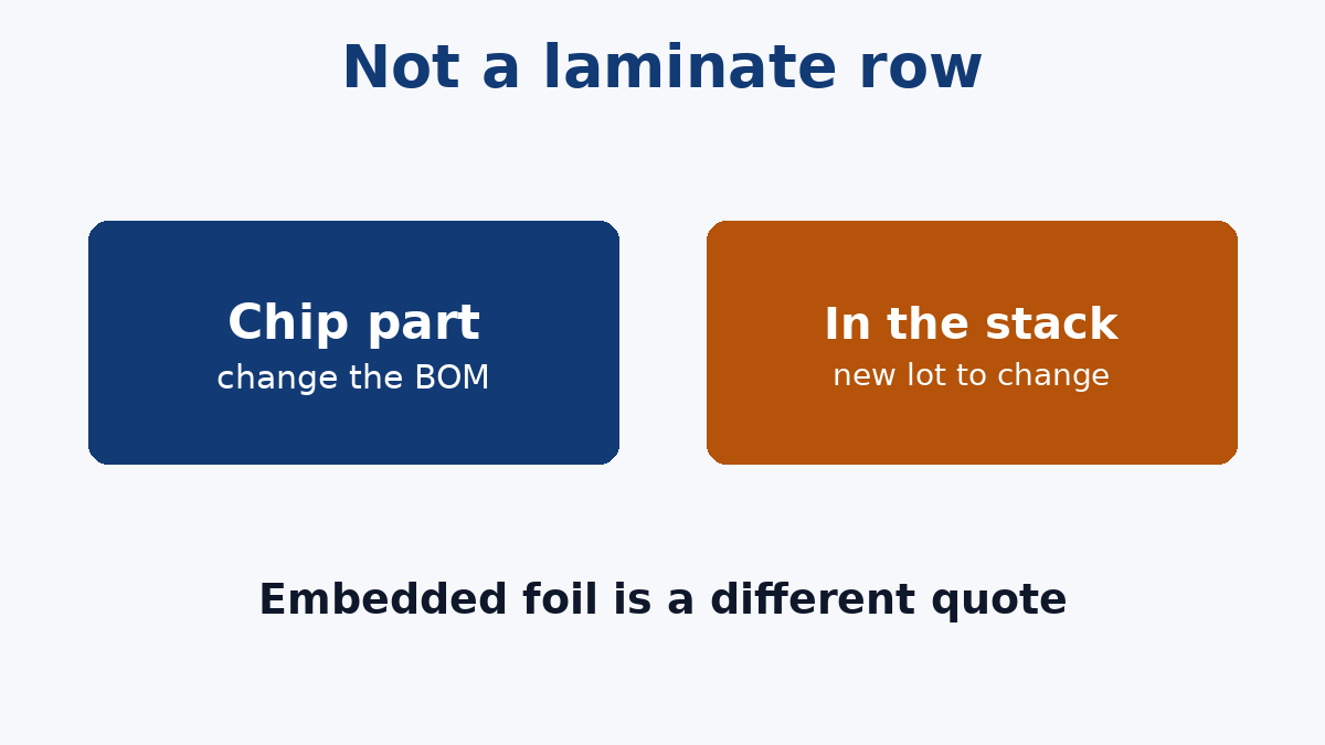
An embedded resistor is a resistive foil buried in the stack and patterned like a trace. Its value is the foil's ohms per square, multiplied by length over width. You design that geometry with the foil's grade. You do not pick 10 kΩ off a reel and drop it in later. Etched tolerance is usually much wider than a one-percent chip unless the board is laser-trimmed, and a trim step is its own process, not a default. Changing the value later is a new lot, not a pair of tweezers.
An embedded capacitor is a thin dielectric between two copper planes. Capacitance follows the area, the thickness and the Dk of that special layer. It can put decoupling directly under a package, which is why dense boards consider it. It also adds a lamination, a material most FR-4 quotes do not stock, and a value you cannot rework. A 100 nF chip that was wrong is a BOM change. A plane capacitor that was wrong is a respin.
Neither belongs in a laminate bake-off. If the quote says "embedded passives" with no foil grade, no sheet resistance, and no layer in the stackup, it is not a material selection. It is a wish. For a prototype, chips are almost always the right call. Move a resistor or a capacitor into the stack only when the density or the mounting inductance is the problem you actually have, and when the foil supplier is named on the purchase order next to the laminate.
What to demand before you pick
- Tg, with the method (DSC or TMA) the same on every sheet.
- Td named separately, not implied by Tg.
- Z-axis expansion across the reflow range, not only the ppm figure below Tg, if barrels are the risk.
- Dk and Df at one stated frequency, with the foil type written beside them.
- Water absorption and CTI only if moisture or surface tracking is the environment, and only against the same conditioning.
- Embedded layers, if any, as their own line: foil grade, sheet resistance or dielectric thickness, and trim or no trim.
The higher number is not the better laminate until you know it was measured the same way.