
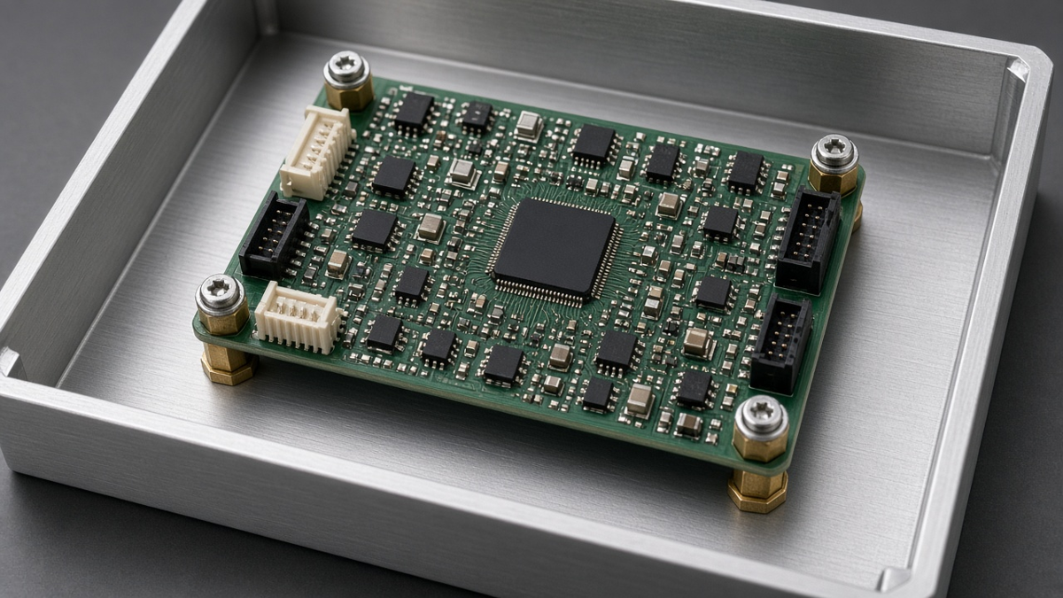
The standoff is usually the last line item anyone thinks about and the first part a field technician touches. It sets the board's height above the chassis, decides whether the board's ground reaches the enclosure, carries vibration into the solder joints, and determines whether the board can be removed without tools or without cracking. Catalog guides list thread sizes and materials. The decision that matters is which hardware suits this product's electrical scheme, environment, assembly line, and service life.
This article is about the hardware itself. The board-side features—hole classes, copper keep-outs, edge clearance, and datum strategy on the drawing—are covered in our PCB mounting and mechanical DFM post. Here we work through the questions that pick the standoff, in roughly the order a mechanical and electrical engineer should answer them together.
Does the standoff carry ground, or must it insulate?
Everything else follows from this. A standoff is either part of the electrical design or deliberately isolated from it.
Metal standoffs as ground bonds. In many products the mounting points tie the board's ground (or a dedicated chassis-ground copper ring) to a metal enclosure. That bond serves EMC—giving common-mode currents and shield currents a short path to chassis—and ESD, where a discharge to a connector shell or front panel must reach chassis without crossing sensitive circuitry. For this to work:
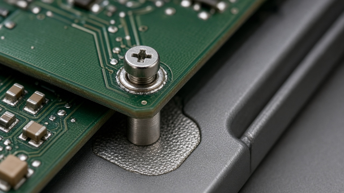
- The board side needs a plated hole with exposed copper ring connected to the intended ground, and no solder mask under the standoff face.
- The chassis side needs a conductive, unpainted contact area, often with a masked or spot-faced surface.
- Contact must be stable over time: plating chosen for low and consistent contact resistance, enough clamping force, and a design that does not rely on a thread alone for conduction.
- The number and placement of bonds matters. Several bonds around the board perimeter and near I/O connectors give low-inductance paths; a single bond far from the connectors does not.
Insulating standoffs. Some designs require the board to float: isolated power supplies where the secondary must not reach chassis, products with a single-point grounding scheme, measurement equipment avoiding ground loops, and boards with hazardous voltages near mounting points. Here the standoff and its screw must not create a path. Options include plastic standoffs, metal standoffs with insulating washers and shoulder bushings, and non-plated holes with copper keep-outs. Check the creepage and clearance from the screw head and washer to nearby copper, not just the hole.
Mixed schemes. It is common to bond at some mounting points and isolate at others—for example, bond near the I/O connector and isolate near a power stage. Write the intent per hole on the drawing, because the assembler cannot infer it.
Metal or plastic, and which metal?
Once the electrical role is set, material follows from strength, environment, and contact behavior.
| Material | Typical reasons to choose | Watch for |
|---|---|---|
| Brass, plated | Good machinability, conductive, common for ground bonds | Plating choice affects contact resistance and corrosion |
| Stainless steel | Strength, corrosion resistance, outdoor or washdown use | Lower conductivity; galling with stainless screws |
| Aluminum | Light weight, thermal contact | Galvanic issues with other metals; softer threads |
| Steel, plated | Strength at low cost | Corrosion if plating is damaged |
| Nylon / polyamide | Insulation, low cost, light loads | Moisture uptake, creep under load, temperature limit |
| Higher-temperature plastics | Insulation near hot parts | Cost and availability |
Galvanic corrosion. Where a standoff contacts a chassis of a different metal in a humid or salty environment, a galvanic couple forms. Aluminum enclosures with brass or stainless hardware are the common case. Plating selection, compatible material pairs, and keeping moisture out of the joint reduce the risk. For outdoor and vehicle products this is not theoretical: corroded bonds increase resistance and can defeat the ESD and EMC design over time.
Plastic creep. Plastic standoffs under constant screw preload relax over time, especially when warm. Clamped joints lose force; snap-in supports loosen. For boards near heat sources or in enclosures that run warm, check the plastic's temperature rating and consider metal hardware with insulating washers instead.
How tall, really?
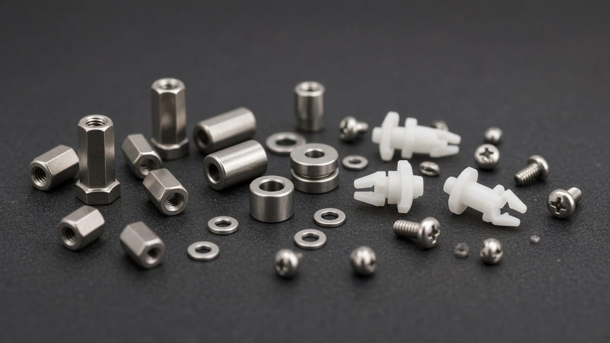
Height is often chosen as "tallest bottom-side part plus some margin." A better approach treats it as a tolerance stack:
- Bottom-side component height, including through-hole lead protrusion and solder fillets, not just SMT body heights.
- Board thickness tolerance and bow, which change the gap at the board's center relative to the standoffs.
- Chassis flatness and any features under the board—ribs, bosses, cable runs.
- Insulation requirements between bottom-side copper or leads and a metal chassis, which may need more than mechanical clearance.
- Thermal needs: airflow under the board or, conversely, contact with a thermal pad that must be compressed by a defined amount.
- Connector alignment: board-mounted connectors that must line up with panel openings fix the board's height within a narrow window.
The last item usually governs. If a front-panel connector must sit centered in a cut-out, the standoff height tolerance plus board thickness tolerance must stay within the connector's alignment allowance. Specify standoff length tolerance accordingly.
Threaded, snap-in, or press-in?
The attachment style is a trade between assembly speed, serviceability, holding force, and electrical function.
Threaded standoffs (male–female, female–female, male–male). The general-purpose choice: strong, repeatable clamping, easy to remove and refit, and compatible with grounding. Costs are part count (screws, washers) and assembly time. Specify screw length so that it engages enough thread without bottoming, and specify torque so that board laminate under the screw head is not crushed.
Self-clinching standoffs in sheet metal. Pressed into a sheet-metal chassis, they become part of the enclosure and remove loose parts from final assembly. They suit sheet-metal enclosures with adequate material thickness and require the enclosure supplier to install them. Grounding through a clinched standoff relies on the clinch interface; confirm it with the hardware supplier for your plating and sheet material.
Snap-in and latching plastic supports. Fast, tool-free, low cost. Holding force is lower and depends on hole size tolerance; vibration can walk boards off them. Removal may damage either the support or the board. They suit light consumer boards in benign environments—see our Consumer Electronics work for typical cases—and rarely suit heavy boards, vibration, or anything needing a ground bond.
Adhesive-base supports. Useful for very light boards or temporary fixtures; adhesive aging and temperature limits make them a poor choice for long-life products.
Board-mounted (solder or press-fit) standoffs. Some standoffs are soldered or pressed into the PCB itself, giving a threaded boss on the board. They simplify final assembly but must be included in the PCBA process—soldered with the rest of the through-hole parts or pressed after soldering—and their holes must match the hardware supplier's recommendation exactly.
What does vibration and shock do to the choice?
Under vibration, the board behaves like a plate supported at the standoffs. The span between supports and the mass on the board determine its natural frequencies and how much it flexes.
- More supports, shorter spans. Adding a standoff near heavy parts (transformers, large capacitors, heat sinks, connectors) reduces flexing at their solder joints.
- Rigid, positive retention. Threaded hardware with thread-locking means or lock washers resists loosening; snap-in supports generally do not.
- Avoid over-constraint. A warped board forced flat onto many rigid standoffs carries a permanent strain into components near the mounts. Where flatness cannot be guaranteed, allow some compliance—slotted holes or a compliant washer at some mounts.
- Heavy parts should not rely on solder alone. If a part is heavy enough that vibration concerns its joints, mount it to the chassis or support it, rather than just adding standoffs.
Vehicle and transport products are where these points matter most; our New Energy Vehicle boards routinely need extra mounting points for this reason.
Is the standoff part of a thermal or current path?
Some standoffs do more than hold the board. On power boards, metal standoffs sometimes conduct heat from a copper pour into the chassis, or carry return current between a board and a metal backplate. If that is intended, treat the standoff like any other conductor in the design.
- Thermal contact depends on the contact area at both ends, the flatness of the faces, clamping force, and the finish. A small hex standoff touching a pad through a ring of solder mask moves very little heat. If heat transfer matters, define a bare copper land, a flat chassis boss, and possibly a thermal interface material, and confirm by measurement on a prototype.
- Current paths through standoffs are generally poor design unless the hardware and contact surfaces are specified for it. Thread contact resistance varies with torque, plating, and corrosion. Where a defined current must flow from board to chassis, a dedicated terminal or bus connection is more predictable than a mounting screw.
- Unintended paths matter too. A metal standoff that touches a heat-spreading copper area tied to a switching node can couple noise into the chassis. Keep switching copper away from bonded mounting points unless the design intends it.
Who installs it, and with what?
Hardware that is easy to specify can still be hard to install.
- Assembly sequence. Standoffs fitted to the board at PCBA level, or to the chassis by the enclosure supplier, or at final box build? Each choice changes who buys, stores, and installs the hardware.
- Tooling. Screw drivers with controlled torque, correct bits, and fixtures that support the board during screwing so the screwdriver force does not flex it.
- Access. Can a driver reach every screw without hitting components? Tall parts near mounting holes block access.
- Kitting. Small hardware is easy to mix up; similar-looking screws of different lengths cause bottoming or insufficient engagement. Distinct lengths and clear kitting reduce errors.
- Torque specification. Write it on the assembly instructions, with a value appropriate to the hardware and the board laminate under the head.
Can the field service it?
Products that will be opened in service need hardware that survives repeated removal.
- Threaded metal standoffs tolerate many cycles; plastic threads and snap-ins wear.
- Captive screws prevent lost hardware inside equipment.
- Ground bonds must be restored on reassembly; star washers or conductive features that are not reused correctly degrade the bond.
- If a technician must remove the board to reach a fuse or connector, consider moving that part instead.
Common mistakes that reach production
- Metal standoffs on a board meant to be isolated, discovered at hipot test.
- Solder mask under a ground-bond standoff, making the bond depend on the screw thread.
- Plastic standoffs near a hot heat sink, loosening after months in service.
- Snap-in supports on a board with heavy connectors, walking loose under cable strain.
- Standoff height chosen without the panel connector alignment, leaving connectors off-center in their cut-outs.
- Aluminum chassis with brass hardware in an outdoor product, corroding at the bonds.
A selection worksheet to fill in before you order hardware
Answer these for each mounting position, not just for the board as a whole:
- Electrical role: ground bond, insulated, or no requirement? If bonded, to which net, and is the chassis contact surface defined?
- Material and finish: chosen for conductivity, strength, corrosion pair with the chassis, and temperature.
- Height and tolerance: derived from bottom-side clearance, insulation distance, connector alignment, and thermal contact.
- Attachment style: threaded, clinched, snap-in, board-mounted, or adhesive, and why.
- Retention: thread-locking, lock washers, or captive features where vibration or service demands them.
- Installer and sequence: who fits it, at which step, with what tool and torque.
- Service: how many removal cycles, and how the ground bond is restored.
- Drawing references: hole class, copper ring or keep-out, and mask opening on the PCB drawing matching this choice.
A standoff that can answer all eight is part of the design rather than an afterthought. If a row cannot be answered yet, that is the conversation to have with the enclosure designer before the board is released—not after the first enclosures arrive.