
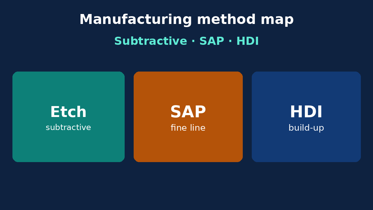
RFQs that ask for an “additive board” or “HDI method” without changing the stack and via plan create EQ noise. Manufacturing methods are process families—subtractive etch, additive/semi-additive copper build-up, sequential HDI lamination, flex roll-to-roll, mechanical punch for simple singles—each implying different materials, vias, and documentation. This article is a method selection map for buyers: when a method change is really a stack/via change, what to name on the RFQ, and which cost traps appear when buzzwords replace build intent. It is not a museum tour of every historical process, and not a duplicate of etch-compensation or drill-control posts.
Buyer decision frame: method follows construction
Ask in order:
- Rigid multilayer vs flex vs rigid-flex vs metal-core?
- Through-via only vs blind/buried vs any-layer HDI?
- Copper feature size and impedance—standard subtractive or finer semi-additive?
- Volume economics—prototype flying probe vs high-volume tooling (punch, R2R)?
Method language on the PO should match those answers. Saying “use additive” while sending a standard subtractive stack with through-holes only wastes quote cycles. See PCB Fabrication Process for process overview and HDI PCB when sequential build-up is truly in scope.
Subtractive patterning: the default most RFQs already mean
Subtractive flow starts with copper foil on laminate, protects wanted copper, and etches the rest. It dominates rigid FR-4 and many flex builds. Buyers should know:
- Fine lines have etch undercut limits—geometry and copper weight interact.
- Outer layers after plate have different finished copper than start foil.
- Impedance coupons must reflect the same etch reality as routed nets.
When your features fit standard subtractive capability, do not invent a method upgrade. Freeze line/space, copper weights, and etch notes. Method = subtractive multilayer lamination + drill/plate—the everyday China fab path.
Additive and semi-additive: when feature size demands it
Fully additive and semi-additive (SAP/mSAP) families deposit copper where needed, enabling finer lines than thick-foil subtractive etch allows. They imply:
- Different process capability and often different fab lines.
- Stack and foil strategies that match the additive flow.
- Cost and lead implications you must accept on purpose.
RFQ language: name minimum line/space and copper, ask if subtractive suffices; only specify SAP/mSAP when capability review says subtractive cannot hit geometry. Do not use “additive” as a synonym for “high quality.”
HDI build-up: sequential lamination is the real change
HDI is less a marketing method than a via architecture + sequential press choice: laser microvias, stacked/staggered vias, possible any-layer constructions. When you ask for HDI:
- Freeze via types, start/stop layers, and capture pads.
- Show build sequence on the stack document.
- Accept registration and yield risk that through-via boards avoid.
If your routing only needs through-holes on six layers, you do not need HDI method language—you need better placement or one more signal layer. Method change without via/stack change is theater.
Lamination, punch, and roll-to-roll: volume and construction gates
Multilayer lamination is not optional once you exceed two layers of copper needing bonded dielectrics—it is the backbone method.
Punching/stamping fits high-volume simple single-sided boards with tolerant features—not fine multilayer.
Roll-to-roll fits high-volume flex when tooling and volume justify continuous flow—not every FPC prototype.
Name these when volume and construction truly match. Quoting R2R for a 50-piece rigid-flex prototype confuses purchasing.
Special processes that are not whole “methods”
Gold fingers, heavy copper, cavity, embedded coin, back-drill, and selective finish are process add-ons on top of a primary method. Call them as named operations on the fab note. Do not relabel the whole job “special method” without the primary stack/via story.
Failure modes from wrong method language
- Quote apples-to-oranges because one vendor assumed HDI and another assumed through-via.
- CAM rebuilds stack when “additive” was aesthetic language.
- Lead time explodes after late HDI discovery.
- Yield crashes when punch-oriented outline meets fine-pitch SMT.
What fab can and cannot fix
Can: declare which method family they will run; propose capability-matched alternatives; align stack/via notes to the chosen family.
Cannot: deliver mSAP geometry on a subtractive traveler you forbade to change; punch a multilayer HDI; make R2R economics work at prototype qty.
RFQ callouts
- Primary construction and layer count.
- Via architecture (through / blind-buried / HDI sequence).
- Patterning expectation (standard subtractive vs fine-line/SAP need).
- Volume band (affects fixture vs flying probe, punch vs route).
- Named specials (back-drill, heavy Cu, fingers).
- Stack PDF locked to the method.
- “No method substitution without EQ.”
Also keep Manufacturing Files consistent with that method—layer names and via charts included.
Common EQ loop
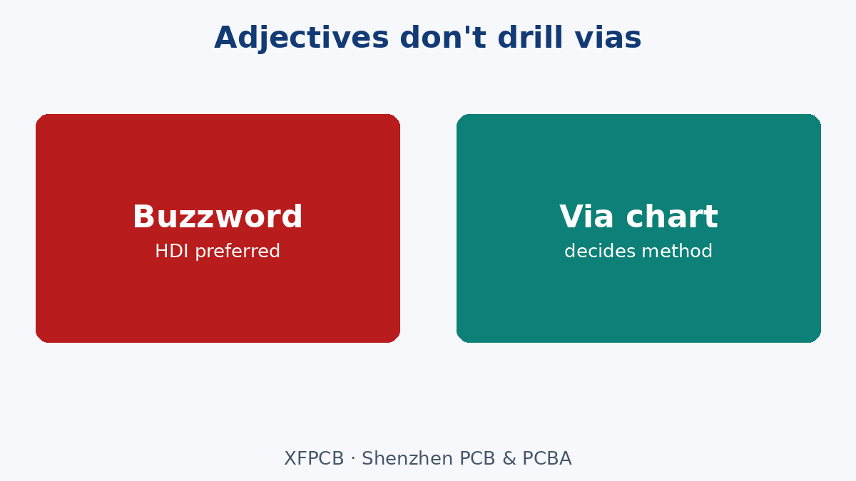
- RFQ says “HDI preferred.”
- Layout still through-via only.
- Vendor A quotes HDI capability premium; vendor B quotes standard multilayer.
- Argument about who is “real HDI.”
- Clarification: via chart shows no microvias—standard method wins.
Break the loop by attaching via chart + stack before method adjectives.
Comparing quotes across method families
When three vendors return three prices, check whether they assumed the same method family. Ask each to state: patterning process, via architecture, and lamination sequence count. A low quote that assumes through-via subtractive against an HDI via chart is not a bargain—it is a mismatch that will EQ later. Normalize method declarations before you normalize price.
Drill and plate as method companions
Mechanical drill, laser drill, and plasma desmear pair with method families differently. HDI laser vias need copper-stop or dielectric-stop strategies tied to the stack. Subtractive through-holes need aspect-ratio honesty. Additive fine lines often accompany tighter registration budgets. Put drill method expectations next to patterning method on the RFQ when mixed (laser + mechanical) builds are planned. Sister posts cover drill controls and QA; here the point is method coupling—do not order laser microvias on a traveler that only budgets mechanical drill.
Panelization and depaneling tied to method
Punch methods imply die tooling and panel strategies different from routed FR-4 arrays. HDI panels may restrict coupon placement. Flex R2R implies slitting and coverlay flows. Name depaneling (V-score, tab route, punch) so assembly fixtures match. Method selection that ignores depaneling creates SMT surprises.
Quality gates differ by method
Flying probe may suffice for subtractive prototypes; HDI may need coupon microsections and via chain tests named explicitly. Additive fine-line may need AOI tuned for new geometries. Attach the test menu to the method—not a generic “full inspection” line. Cross-link your inspection scope map when risk is high.
Documentation package that locks method
Gerbers/ODB++, via chart, stack with build sequence, drill files, and a one-page method statement (“subtractive multilayer, through-via only, no HDI”) prevent adjective wars. If HDI, include laser via table and lamination steps. If SAP, include line/space targets and copper thickness strategy. Purchasing should attach that one-pager to every quote request.
When plants propose method changes
A capable plant may propose converting a marginal subtractive fine-line job to SAP, or converting an over-specified HDI to staggered buried vias on fewer presses. Treat proposals as ECOs: update drawings, re-sim if needed, re-quote. Oral “we will handle it” is not method lock.
Multiwire and niche methods
Discrete wiring / multiwire and other niche approaches exist in limited supply chains. Do not put them on an RFQ unless the design literally requires them and you have confirmed a vendor. Most overseas commercial electronics never need this noun—resist catalog curiosity on the PO.
Sustainability and waste talking points without greenwash
Additive pitches sometimes claim less copper waste. Whether that matters to your program is a corporate decision—not a substitute for geometry requirements. Do not select method on sustainability slogans alone; select on capability, then discuss waste if your ESG process requires it. No invented recycling percentages here.
Cost traps without invented prices
Buying HDI language without microvias pays for fear. Avoiding semi-additive when geometry truly needs it pays for scrap. Mixing punch economics with multilayer expectations fails. Changing method mid-program resets CAM, coupons, and sometimes fixtures. Select method from geometry and volume—then freeze.
How method interacts with materials and finishes
PTFE, ceramic-filled, and some high-speed systems change drill and lamination recipes inside the same “subtractive multilayer” family. Method family stays subtractive; process recipe still needs material declaration. Likewise, ENIG vs HASL is finish, not method—but finish capability may differ on additive lines. Keep materials, method, and finish as three callouts, not one buzzword.
Prototype vs mass-production method shifts
A prototype may use routed outlines and flying probe; mass production may add punched singles, dedicated fixtures, and different panelization. Those are still usually the same patterning family. Document the intended production method early if NPI must represent production risk. Silent method shifts between EVT and MP invalidate lessons learned.
Flex and rigid-flex method notes
Flex often uses subtractive copper on polyimide with coverlay—sometimes R2R at volume. Rigid-flex adds sequential or book-build complexity. Do not paste rigid multilayer method assumptions onto flex RFQs. Name construction first (Flexible PCB / rigid-flex capability as needed), then method details.
Training buyers and engineers on method nouns
Create an internal cheat sheet: subtractive = etch away copper; SAP = build copper for fine line; HDI = sequential microvia build; R2R = high-volume flex; punch = high-volume simple singles. Require every RFQ to pick one primary patterning family and one via architecture statement. That shared language cuts EQ time more than any brochure.
Interaction with impedance and etch compensation
Subtractive impedance control depends on etch compensation and dielectric height. SAP changes the geometry assumptions. If you switch method families, revisit impedance notes—do not keep the old coupon table blindly. Method and impedance are coupled controls on high-speed boards.
China fab capacity reality check
Most XFPCB-class rigid work is subtractive multilayer with optional HDI lines. Confirm capacity before promising SAP or exotic niche methods on a schedule. Method aspiration without line capacity is a schedule risk. Ask during EQ which campus and process line will run the job, and freeze that when risk is high.
Incoming inspection against method declarations
When first articles arrive, check that the traveler’s process stamps match the method statement: via types present on X-ray or microsection, line geometry consistent with subtractive vs SAP expectations, and lamination count if HDI sequential was claimed. Method fraud is rare; method mismatch from soft RFQs is common. Catch it at FAI, not after MP ramp.
Spare capacity and second-source method parity
If you dual-source, both plants must run the same method family and via architecture—or you must qualify differences. A second source that only offers through-via while the primary runs HDI is not a true alternate. Method parity belongs in the dual-source checklist beside material family parity.
Communicating method to assembly partners
Assemblers need to know if boards are thin HDI, heavy copper, or MCPCB because fixtures and profiles change. Pass the method one-pager to SMT with the board rev. Do not assume fab-to-assembly handoff includes process context—attach it.
Method selection workshop (30 minutes)
Run a short workshop at schematic freeze: display via chart and stack; ask whether microvias exist; ask minimum line/space; ask volume band; then circle subtractive, SAP, or HDI. Record the circle on the method one-pager and attach it to the RFQ. Workshops prevent adjective-only RFQs better than email threads.
Reverse engineering competitor boards carefully
Seeing microvias on a competitor teardown does not mean your RFQ needs HDI language—your routing density might differ. Copy requirements from your CAD, not from tear-down photos. Method follows your geometry.
Closing: method is a consequence of the build
Manufacturing method selection is the language of stack, via, geometry, and volume—not a menu of cool nouns. Map subtractive, additive/SAP, and HDI build-up to what your drawings actually require, write that map on the RFQ, and forbid silent swaps. XFPCB will run the process family your frozen stack and via chart imply—bring those charts, and method adjectives become unnecessary.
Release test: if you delete every method buzzword from the RFQ and only stack plus via chart remain, can the plant still know what to build? If yes, your method selection is healthy. If no, you were relying on adjectives—and adjectives do not drill microvias.