

“PCB design rules” articles often read like placement poetry: keep parts neat, traces short, corners soft. Those habits help. They are not what a China fab means when CAM rejects a board that already “passed DRC.”
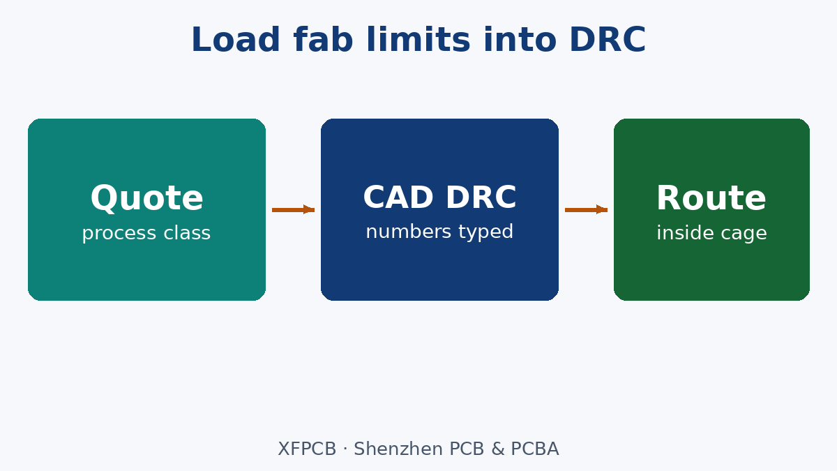
This post is the factory meaning of design rules for overseas buyers and engineers: load the quoted capability numbers into the CAD rule set before you route—min line/space, annular ring, drill-to-copper, edge clearance—then place and route inside that cage. It is not a full EMI cookbook, not a rework-prevention essay, and not the factory EQ-loop DFM review (those are separate posts).
Design rules are a contract with a process class
A fab quotes a process class: finished copper, min trace/space, min drill, annular ring, solder-mask dam, and so on. Your CAD design-rule check (DRC) is only as honest as the numbers you typed. Default “IPC-ish” templates from an EDA library are not that quote.
Before layout:
- Pick the fab process class you will buy (prototype vs production density).
- Enter min L/S, drill, pad, annular ring, copper-to-outline, and mask rules from that class.
- Route and place against those rules.
- When you must break a rule, change the quote class—or accept EQ and cost—not hope CAM will waive it.
Our PCB Fabrication Process page is the process seat; the numbers still have to live in your rule set.
Placement still matters—but as yield and heat, not vibes
Keep functional blocks together and shorten nets that care. Separate hot parts from sensitive ones. Leave grip and connector keep-outs. Those are real. They do not replace annular-ring math. A neat schematic block that uses 3 mil lines on a 5 mil quote is still a CAM reject.
Routing rules that survive manufacturing
Useful habits that map to copper geometry:
- Prefer the simplest stack that meets the electrical ask (do not add layers to hide a rule break).
- Avoid acute corners where the fab and impedance both suffer; 45° or smooth bends are the usual production language.
- Orthogonal adjacent layers reduce broadside coupling; long parallel overlaps need a reason.
- Length-match only the nets that need it—matched junk is still junk.
- Thermal relief on plane ties helps soldering; high-current pads may need solid ties—write the exception.
- Edge clearance must clear V-score, rail, and connector mate—not a borrowed “5 mm” slogan. Use the outline and process you actually ordered.
Power and ground want low impedance: planes on multilayer, short returns on two-layer. That is SI/PDN, still bounded by the fab’s min copper and via rules.

Trace width and spacing without invented universals
Width follows current, temperature rise, and impedance—not a blog’s “0.2 mm typical.” Spacing follows voltage, process, and copper balance. Inner layers often carry less current for the same width than outer. When the article lists mils as global truth, ignore the number and keep the method: calculate or use the fab’s chart for your copper weight, then set DRC to the tighter of electrical need and process min.
Impedance-controlled nets need width, dielectric, and foil in the stack note—not only a DRC clearance. Our Impedance Control PCB page is that callout.
What DRC pass does not mean
Passing your local DRC does not mean CAM will be silent if the rule set was wrong, the stack note disagrees, or drill charts and slots were never constrained. Factory DFM review and EQ are the next gate. Do not treat this post as that review.
What we are not claiming
No universal mil/mm tables as XFPCB defaults, no claim that 45° corners fix EMI, no 5 A thermal-relief law as a standard, and no replacement for the DFM-mistakes or EQ-loop posts. Load fab limits into CAD before you route. Then the soft “keep traces short” advice has a cage it can live in.