

The advantages of surface mount technology are well rehearsed: smaller parts, components on both sides, automated placement, shorter leads with lower parasitic inductance, fewer drilled holes. For a new design, those advantages arrive almost by default, because nobody starts a fresh layout with through-hole resistors.
The more interesting case, and one we see regularly at our Shenzhen assembly lines, is the older product. A board designed years ago around through-hole parts is still selling. Through-hole versions of some of its components are getting harder to buy, the wave soldering step is the slowest part of its build, and someone asks whether converting it to SMT would make it cheaper and easier to produce.
It often does. But the advantages of SMT on a converted design are not automatic. Some appear immediately, some only if the layout is reworked properly, and a few come with new risks that the original through-hole design never had. This article looks at SMT's advantages through that conversion lens: which ones you actually collect, what has to be re-verified, and how to plan the change so that the first SMT build does not become an expensive experiment.
Which advantages show up on a converted board
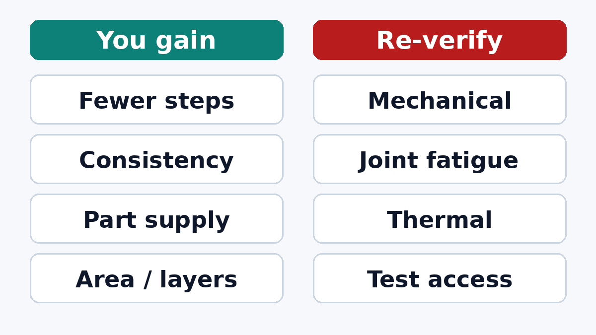
Fewer process steps. On a mixed-technology board, every through-hole part means insertion (often manual) followed by wave, selective or hand soldering. If conversion removes all or nearly all through-hole parts, the board can go through printing, placement, reflow and inspection, with no secondary soldering at all. This is usually the single biggest gain for a legacy board, more than board area. On a well-run SMT PCB assembly line, removing the secondary operations also removes the most variable steps from the traveler.
Consistency. Machine-placed, reflowed joints are more repeatable than hand-inserted, wave-soldered ones, especially when wave soldering a board that was never laid out with wave in mind.
Component availability. Many passive and logic parts are now produced mainly or only in surface-mount packages. For long-lived products, conversion is sometimes driven less by cost than by being able to keep buying parts.
Board area and layer count, maybe. The board outline is often fixed by the enclosure, so the area saved does not always turn into a smaller board. It may instead let you move everything to one side, which avoids a second reflow pass, or simplify routing enough to drop layers. Whether that pays depends on whether you are willing to redo the layout rather than just swap footprints.
Electrical performance. Shorter leads and smaller packages lower parasitic inductance, which helps decoupling and fast edges. On an old, slow design, this is rarely why you convert, but it can change behavior: faster edges from modern parts can create EMI problems the old design never had. More on that below.
Part by part: what converts easily and what does not
Not every through-hole part should become SMT. A useful first pass sorts the BOM:
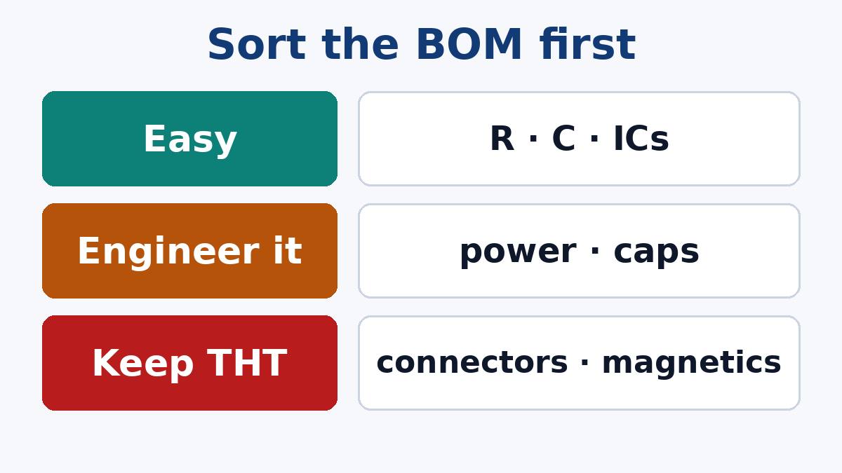
Easy conversions. Resistors, small capacitors, diodes, small-signal transistors, logic and most ICs. Surface-mount equivalents exist with the same function, often from the same manufacturers. Check the electrical rating, not just the value: a through-hole resistor may have a higher power or voltage rating than the SMT chip that matches its value.
Conversions that need engineering. Power semiconductors in packages such as TO-220 often have surface-mount equivalents, but a through-hole part bolted to a heat sink and a surface-mount part dissipating into copper are very different thermal designs. The SMT version needs copper area, thermal vias to inner planes or the other side, and a check that the board can carry the heat. Electrolytic capacitors are available in SMT, but large values and high ripple ratings may be awkward, and their reflow temperature limits must be checked. Crystals, inductors and relays usually have SMT versions with different footprints and characteristics.
Parts that often should stay through-hole. Connectors that take repeated mating force or cable strain, large transformers and chokes, heavy terminals, and parts that carry a mechanical load. Surface-mount connectors with through-hole hold-down pegs or retention features exist and work well in many products; a connector held only by its solder pads in a product that sees cable pulls is a field failure waiting to happen.
The outcome is often a board that is mostly SMT with a handful of through-hole parts. That still collects most of the benefits, especially if those remaining parts can be soldered by pin-in-paste reflow rather than a separate wave step. Pin-in-paste needs attention to hole size, paste volume and component temperature rating, and a PCB SMT stencil designed for the overprint or step required; discuss it with the assembler during the layout, not after.
What you have to re-verify
This is the part that conversions most often skip. A through-hole design that has worked in the field for years has implicitly passed a set of tests that the converted design has not.
Mechanical robustness. Through-hole leads anchor parts through the board. Surface-mount joints rely on the pad and the solder fillet. Tall or heavy SMT parts in a product that sees vibration or shock may need adhesive, mechanical support or a different package. Ceramic capacitors are sensitive to board flexing, so placement near board edges, mounting screws, connectors and depaneling lines needs care that a through-hole layout never required.
Solder joint fatigue. Leadless and large ceramic packages experience more strain from thermal expansion mismatch than leaded through-hole parts, whose leads flex. If the product sees wide temperature cycling, a converted design should be evaluated for it, not assumed to inherit the old design's history.
Thermal behavior. Every power part that moved from a heat sink to copper needs measurement under real load, not just a datasheet calculation.
Creepage and clearance. Surface-mount packages usually have smaller pin spacing. On boards with mains voltages or isolation requirements, check that the SMT package and its pad layout still meet the required distances, and that removing through-holes has not removed a slot or gap that was part of the isolation design.
EMI. Modern logic parts with faster edges than the obsolete parts they replace can radiate more. If the product was certified for emissions, plan a pre-compliance check.
Test access. On many legacy boards, through-hole leads on the bottom side doubled as test points for bed-of-nails fixtures. After conversion those points may disappear. Add test pads, or plan on flying probe testing with the probe access it needs.
Field repair. If the product is repaired at board level in the field, a through-hole part is easy to replace with a soldering iron; a fine-pitch SMT part may need hot air and skill. Decide whether that matters before converting.
A practical conversion plan
- Sort the BOM into easy, engineering-needed and stay-through-hole, as above. This determines how much benefit is available.
- Decide the scope. Footprint swaps on the existing outline collect the process and availability gains. A real relayout collects area, single-sided placement and routing gains, and lets you fix layout weaknesses at the same time. The relayout costs more engineering but often pays for itself.
- Design for the new process. Fiducials, panelization for reflow, component spacing for AOI and rework, test pads, and orientation conventions that suit the line.
- Plan the remaining through-hole parts. Group them, choose pin-in-paste or selective soldering, and keep their keep-out areas clear. If some must remain, the through-hole assembly route should be specified rather than left to the assembler.
- Build a qualification lot. First article inspection, X-ray where there are bottom-terminated parts, thermal measurements, and whatever environmental testing the product's history justifies: thermal cycling and vibration for industrial or vehicle products.
- Treat it as a new revision. New part number or revision, new BOM, new drawings, and a clean break so old and new stock are not mixed.
Is it worth it?
For a low-volume product with few remaining years of life, the engineering and qualification cost may outweigh the savings, and buying through-hole parts while they last can be the right answer. For a product with steady volume and a long future, conversion usually pays back through simpler assembly, better consistency and secure component supply.
If you are considering a conversion, send us the current BOM and drawings. Our engineers can sort the parts, flag the ones that need engineering, and propose which through-hole parts to keep and how to solder them, before you commit to a relayout.