
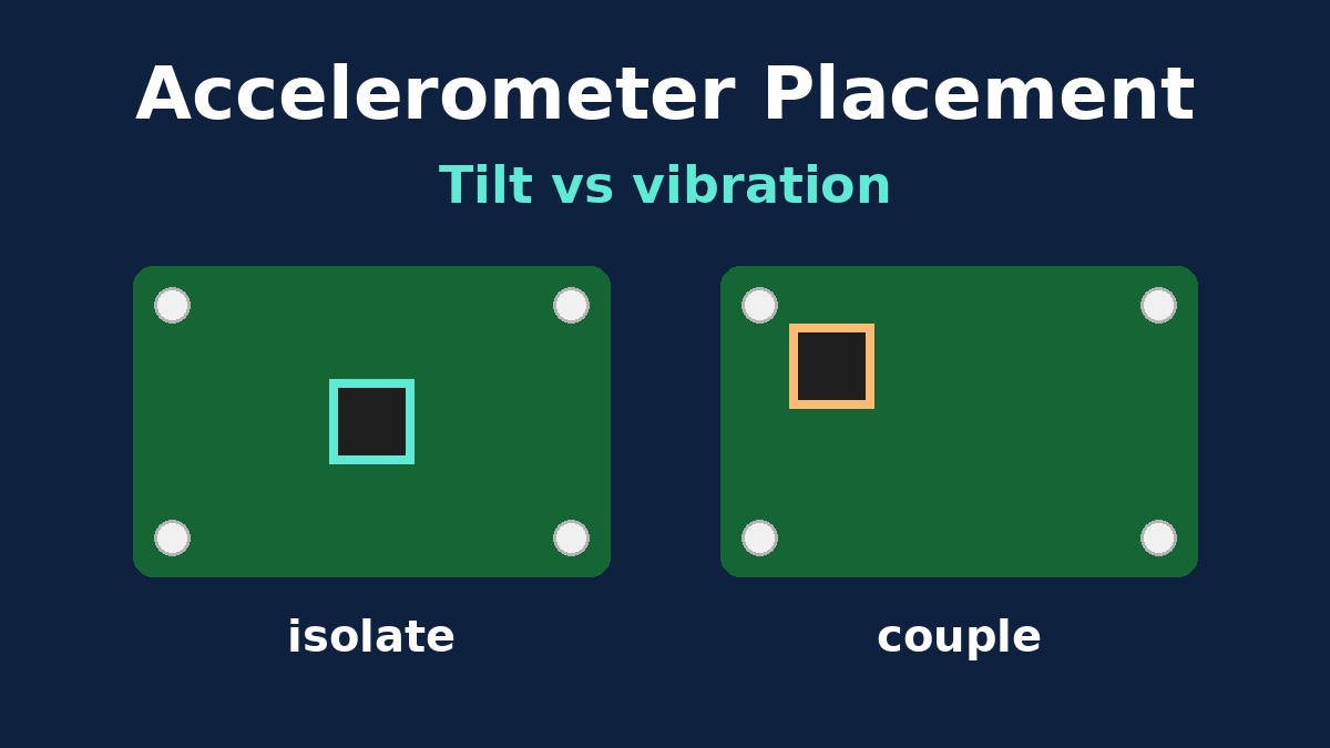
An accelerometer doesn't measure the product. It measures whatever it's soldered to, which is the PCB. Every bend, twist, resonance and temperature gradient in the board is passed straight to the sensor. That's why accelerometer layout advice tends to be mechanical rather than electrical.
Most of that advice says the same thing: keep the sensor away from screws, edges and stress. For a tilt sensor that's right. For a vibration sensor it can be exactly wrong. The two jobs want opposite things from the mechanical path between the sensor and the outside world, and a layout that's good for one can be poor for the other.
This article separates the two cases, then covers what both share and the assembly steps that move a MEMS accelerometer's offset after the board leaves layout.
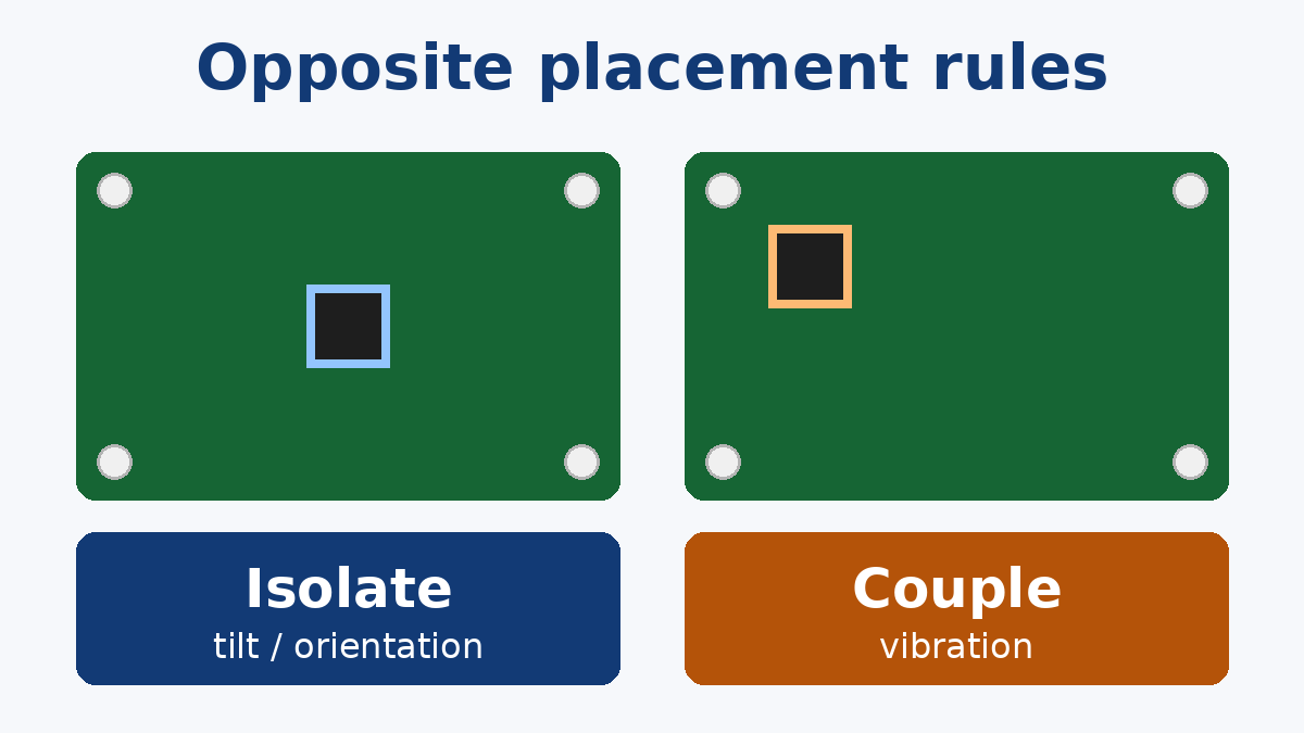
Two jobs, two goals
Static and low-frequency sensing covers tilt, orientation, inclination, step counting and wake-on-motion. The signal of interest is gravity, or slow motion, and the accuracy that matters is the zero-g offset. The enemy is anything that adds a false, slowly changing signal: mechanical stress in the package, board bending and temperature gradients. The goal is to isolate the sensor from the board's mechanical life.
Dynamic sensing covers vibration and condition monitoring, impact detection and machine health. The signal of interest is the motion of the machine or structure, often at hundreds or thousands of hertz. The enemy is a mechanical path that changes that motion before it reaches the sensor, by amplifying it at a board resonance or soaking it up in a loose mount. The goal is to couple the sensor as rigidly as possible to the thing being measured.
Placement for tilt and orientation
For static sensing, the aim is a quiet, unstressed spot:
- Away from mounting points. Screws, standoffs, snap features and shield clips put local stress into the board, and tightening them changes that stress. Sensor vendors' mounting guidance commonly warns against stress maxima, such as the point between diagonally opposed screws, and against over-constraining the board with redundant fixing points.
- Away from edges, cutouts and V-score lines. These areas bend most during handling and depaneling.
- Away from heat. Processors, regulators, chargers, power inductors and batteries create temperature gradients that drift offset. Distance helps, and so does keeping heat-carrying copper pours from running under the sensor.
- Square to the board axes. Firmware assumes the sensor's axes line up with the product's. As an illustration, a 1° rotation between the two couples about 1.7% of one axis into another (sin 1° ≈ 0.017). Placement accuracy on the board is usually good; the larger errors come from how the board sits in the enclosure, which is why calibration happens in the finished product.
Under the package, follow the vendor's land pattern and its guidance on what can sit beneath it. Many recommend no vias or traces under the sensor, symmetrical pad escapes, and narrow traces leaving each pad so that the solder joints pull evenly.
Placement for vibration monitoring
For dynamic sensing, the rules reverse:
- Close to the mounting point. The sensor should sit on the shortest, stiffest path from the machine. Near the mounting screw or stud is often the right place, not the wrong one.
- On a stiff board. A thicker board, a smaller unsupported area, extra fixing points or a stiffener all raise the board's natural frequencies. A board that flexes like a drumskin will add its own resonance to the measurement.
- No cantilevers. A sensor on a daughterboard hanging off a connector, or on a flex tail, measures the daughterboard as much as the machine.
- Firm, consistent mounting. Screws need to stay tight. Rubber grommets and soft gaskets, which are useful elsewhere, decouple the sensor from the vibration it's meant to see unless that's intentional.
The reason resonance matters so much is that acceleration rises with the square of frequency. As an illustration, a vibration of just 0.1 mm amplitude at 100 Hz is an acceleration of about 4 g: (2π × 100 Hz)² × 0.0001 m ≈ 39 m/s². If the board resonates inside the band you're measuring, small motions of the machine become large motions of the sensor, and the data describes the board rather than the machine. The practical rule is to keep the board's first resonance well above the highest frequency of interest, and to check it with a tap test or on a shaker if you can.
Our Industrial Control page covers the cabinet heat, machinery vibration and electrical transients that boards in these environments have to live with.
What both cases share
Some layout points apply whichever job the sensor does:
- Decoupling at the supply pin, with a short loop to ground, as the datasheet shows.
- A quiet reference. Keep switching regulators, motor drivers and radio power amplifiers away from the sensor's ground return. On mixed-signal boards, a solid ground layer under the sensor area helps; our 4-Layer PCB page compares common four-layer stackup choices with a continuous ground plane.
- Short digital lines. I²C and SPI aren't demanding, but short, direct traces away from noisy areas avoid surprises.
- Axis marking on the silkscreen. A small X/Y/Z arrow by the sensor makes it easy to check firmware axis mapping against the hardware.
- Test access to supply and interrupt pins for bring-up.
Assembly steps that move the offset
A well-placed sensor can still have its offset shifted by what happens during and after assembly. These are the points worth writing into the assembly notes:
- Reflow, not hand soldering. MEMS sensors are designed for machine placement and reflow. Hand soldering heats the package unevenly and can leave residual stress. Rework should follow the vendor's guidance.
- Even paste on every pad. Uneven solder volume tilts the package and loads the joints unequally. Vendors often specify stencil and paste volume guidance; follow it.
- No solder on the package sides. Some land grid array packages expose internal traces at their edges, and vendors prohibit solder climbing them.
- Cleaning method. Several MEMS vendors advise against ultrasonic cleaning or caution about it, because ultrasonic energy can excite the sensing structure. State the allowed cleaning method.
- Depaneling. Snapping a V-scored panel or breaking tabs bends the board. Keep the sensor away from break lines, or specify routed depaneling.
- Coating, potting and underfill. All three can change the stress on the package. Use them near the sensor only where the datasheet allows, and mark a keep-out on the assembly drawing otherwise.
- Test fixtures and final assembly. Bed-of-nails probes and enclosure screws both push on the board. Keep probe points away from the sensor area and specify screw torque.
- Time before calibration. Boards relax for some time after reflow. At least one sensor vendor recommends waiting several hours before in-line calibration.
Our SMT PCB Assembly page describes how stencil design, placement data and reflow profiles are aligned before boards reach the line, which is where most of these points are settled.
Checking the result
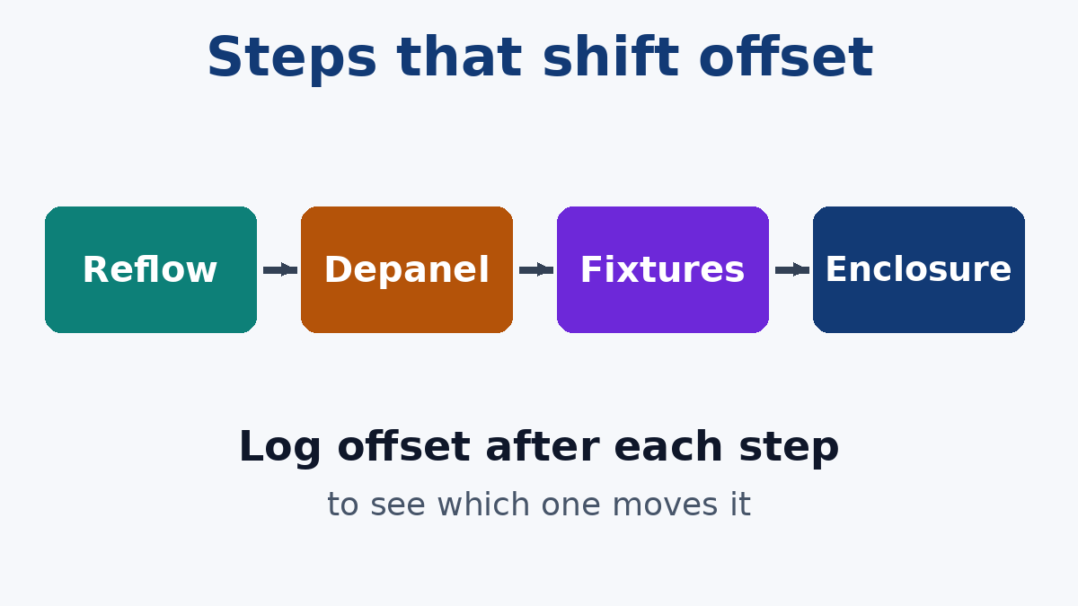
For static sensing, the simplest test is a multi-position check: hold the board still with each axis pointing up and then down. Each axis should read close to +1 g and −1 g, and the midpoint gives its offset. Recording the offset at bring-up, after depaneling and after enclosure assembly shows which step moves it, which is far more useful than a single final number.
For vibration sensing, compare the sensor's output with a reference accelerometer on the same mount, or sweep the assembly on a shaker and look for peaks that come from the board rather than the input.
A short checklist
- Decide whether the sensor's job is static or dynamic before placing it.
- Static: isolate from screws, edges, heat and break lines.
- Dynamic: mount close to the fixing point on a stiff board, with no cantilevers.
- Follow the vendor's land pattern and under-package guidance.
- Put reflow, cleaning, depaneling, coating and screw torque rules in the assembly notes.
- Measure offset after each assembly step, and check board resonance for vibration designs.
The sensor will measure the board either way. The layout decides whether that's what you want.