
Lists of metal core PCB applications all look alike: LED lighting, automotive, power supplies, motor drives, communications. The list is correct, and it tells you almost nothing about how to specify the board. A metal core board in a street light and one in a vehicle headlamp may look identical, but they fail for different reasons, and the drawing should reflect that.
This article goes through the main applications from the factory's point of view. For each, it asks what the application demands from the board beyond simply moving heat, what tends to go wrong, and what belongs on the drawing. How heat actually flows through the board, and how to size that path, is covered in our companion article on metal core heat dissipation; here the focus is on what each use case needs.
A quick reminder of the construction: a copper circuit layer, a thin thermally conductive dielectric, and a metal base, usually aluminium, sometimes copper. Most metal core boards are single-layer, with components on one side only.
LED lighting
This is the largest application, and the one where a metal core board is usually the obvious choice. Arrays of mid-power or high-power LEDs on a single layer, with the base mounted to a housing or heat sink.
What it demands beyond cooling:
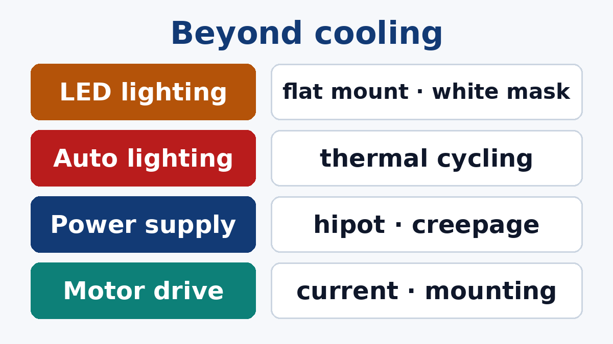
- Surface reflectivity and colour stability. White solder mask is common, and it has to stay white after reflow and years of light and heat exposure. Ask about the mask's behaviour under heat and UV if the board is visible.
- Flatness and mounting. The base must sit flat against the housing. Bowing after reflow or uneven mounting screws leaves air gaps that undo the thermal design.
- Long, thin outlines. Linear lights need long strips, which affects panel utilisation and how the boards are separated.
Typical failure modes: LEDs running hot because of poor contact between the board and the housing; solder voids under the LED thermal pads; discoloured mask in visible fixtures.
Our LED Lighting page covers the wider product range we build for.
Automotive lighting
Headlamps, tail lamps and signal lights use high-power LEDs on metal core boards in a much harsher thermal environment.
What it demands beyond cooling:
- Thermal cycling resistance. Aluminium expands several times as much per degree as the ceramic body of a typical high-power LED package. Every temperature cycle strains the solder joints between them. Over thousands of cycles, that is the dominant failure mechanism. Dielectrics with lower stiffness, the right solder alloy and pad design all play a part, and the combination should be qualified by thermal cycling.
- Copper base for high flux. Very compact, high-output light sources sometimes move to copper base boards, including constructions in which the LED thermal pad sits directly on a raised part of the copper base rather than on the dielectric.
- Documentation and traceability expected by automotive customers.
Typical failure modes: cracked solder joints after thermal cycling; delamination of the dielectric at high temperatures. For the broader requirements of vehicle electronics, see our Automobile Electronics page.
Power conversion
Switching power supplies, DC-DC converters, battery chargers, solar and inverter power stages use metal core boards under power semiconductors and sometimes magnetics.
What it demands beyond cooling:
- Dielectric breakdown voltage. The thin dielectric layer is the insulation between the circuit and a metal base that is usually connected to a grounded housing. On mains-connected products, it must withstand the required test voltage with margin. Thermally conductive dielectrics trade thickness against conduction, so the dielectric choice is a safety decision as well as a thermal one. Specify the hipot test voltage and duration on the drawing.
- Creepage to the base. At board edges, mounting holes and cut-outs, the metal base is exposed or close to the surface. Creepage distances from high-voltage copper to those edges must be designed in, and edges must be free of burrs from routing or scoring.
- Mixed layouts. Power stages often need control circuits nearby. A single-layer metal core board restricts routing; some designs use a separate FR-4 control board, or a multilayer metal-based construction.
Typical failure modes: hipot failures at mounting holes or edges; dielectric breakdown under surge; heat trapped under parts because of voids in the thermal interface below the board.
Motor drives and industrial power
Motor controllers, solid-state relays, industrial power modules and heaters.
What it demands beyond cooling:
- High current. Thick copper on the circuit layer, which affects minimum spacing and etching.
- Isolation and mechanical mounting. Boards are bolted to heat sinks and subjected to vibration; mounting holes, washers and torque need thought, because cracking the dielectric at a mounting point can create a short to the base.
- Through-hole power components. Holes through a metal base must be insulated from it, which adds process steps. Where possible, surface-mount power packages suit metal core boards better.
RF power
Some RF power amplifier and transmitter modules use copper or aluminium base boards. Here the base may serve as the RF ground and the heat path at the same time, which changes the requirements: electrical connection between the circuit ground and the base, flatness for mounting to a chassis, and dielectric properties suited to RF rather than only to heat. These are specialised builds that should be discussed with the fab at the design stage.
When not to use a metal core board
The application list can make metal core sound like the default answer for anything warm. It is not:
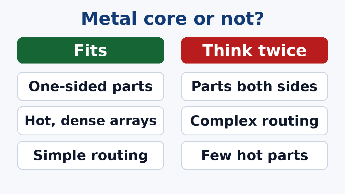
- Components on both sides. A standard metal core board has components on one side only.
- Complex routing. One circuit layer limits routing. Multilayer metal-based boards exist but cost far more.
- Moderate heat. Many designs dissipate their heat adequately through an FR-4 board with thermal vias and copper planes, mounted to a heat sink.
- Large boards with a few hot parts. Making the whole board metal core for a few hot parts may be wasteful; a small metal core sub-board, or local copper inserts in an FR-4 board, can be more economical.
What to put on the drawing, by application
- All: base metal and thickness, dielectric thermal conductivity class and thickness, copper weight, solder mask colour, finish, flatness requirement
- LED: mask colour stability requirements if visible, thermal pad design, panel and separation method
- Automotive lighting: thermal cycling requirement and the qualification test, traceability
- Power conversion: hipot voltage and duration, creepage distances to edges and holes, edge quality
- Motor and industrial: copper weight, mounting hole insulation, through-hole requirements
Our Metal Core PCB service page lists the constructions we build. If you are deciding whether your application needs a metal core board, send us the power levels, operating environment and outline, and our engineers will suggest the construction, or tell you if FR-4 with a good thermal design would do the job.