

Multilayer ceramic capacitors are the most numerous parts on most circuit boards, and individually they're very reliable. Their weak point is mechanical. An MLCC is a small block of fired ceramic soldered rigidly to a board made of glass and resin, and ceramic doesn't bend. When the board flexes, or when the part is heated too quickly, the ceramic can crack. The crack is usually invisible, often passes every test at the factory, and may only turn into a failure months later in the field.
Choosing an MLCC's value, voltage and dielectric is covered in our capacitor selection article. This one is about what happens to the part after it's chosen: where cracks start during assembly and handling, what the layout can do to prevent them, which part options help, and how to check a process before it ships cracked boards.
Why MLCCs crack and why it's hard to catch
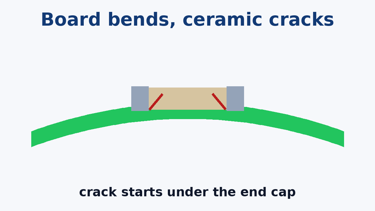
An MLCC is built from many thin ceramic layers with metal electrodes between them, fired into a solid block, with metal terminations on each end. The solder joints at those ends hold it rigidly to the board. If the board bends, the board surface stretches or compresses, the joints pull on the ends of the part, and the stress concentrates in the ceramic just inside the termination. A typical flex crack starts there and runs diagonally into the body.
What makes these cracks troublesome is how they fail. A crack that cuts across the electrode layers can lose some capacitance, which is rarely noticed. A crack that connects electrodes of opposite polarity creates a leakage path. With voltage and moisture over time, that path can grow into a low-resistance short. On a capacitor connected directly across a supply, a short can overheat the part and the board around it. That's why cracks matter even though most of them produce no immediate symptom.
Two kinds of crack are common:
- Flex cracks, from bending the assembled board.
- Thermal shock cracks, from heating or cooling the part too fast, typically during hand soldering or rework.
Where boards bend after assembly
Board flexing almost never happens in the reflow oven. It happens in the steps after it, and each one has a typical spot on the board where cracked capacitors cluster:
- Depaneling. Snapping a V-scored panel by hand, cutting with a wheel cutter, or breaking off tabs bends the board along the separation line. Capacitors close to that line take the most strain.
- In-circuit and functional test fixtures. Probes push on the board. If the board isn't supported close to the probes, it deflects between support points.
- Screws and standoffs. Tightening a screw into a standoff that isn't level with the others bends the board locally around the hole.
- Connector mating. Pushing a connector onto a board that isn't supported behind the connector flexes the area around it, sometimes many times over the product's life.
- Housing assembly. A board pressed into a housing that doesn't quite fit, or clipped into a frame that holds it in a bow, stays under strain permanently.
- Board warpage itself. A board that warps during reflow and is then forced flat during later steps puts strain on everything on it.
When a failure analysis shows cracked capacitors, their location usually points to the cause. Cracks clustered along a panel edge point to depaneling, around a hole to screw mounting, and near a connector to mating forces.
Layout rules that prevent flex cracks
Most flex cracking can be designed out at the layout stage, at no cost to the board.
Keep MLCCs away from bend sources. Leave distance between capacitors and V-score lines, breakaway tabs, mounting holes and connectors that get mated by hand. The further away, the lower the strain, and large case sizes need the most distance.
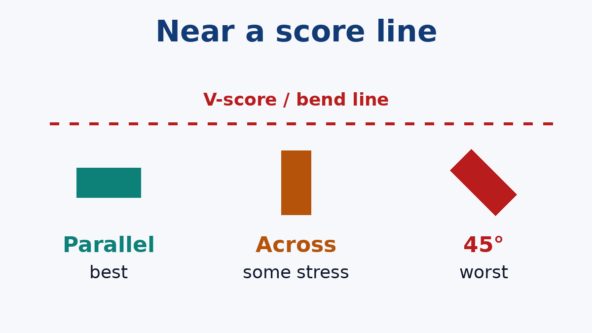
Orient them along the bend line. If a capacitor has to be near a score line or a screw, turn it so that its long axis runs parallel to the line the board will bend around. The board then bends across the part's width rather than stretching it end to end. Research on flex cracking has shown that parts placed at 45° to the bend are the most vulnerable, so diagonal placement near a bend source is the one to avoid.
Prefer smaller case sizes where the board will flex. Longer parts span more bent board and take more strain. Large MLCCs (1210 and up) are the most susceptible, especially on thin boards. IPC/JEDEC-9704A, the strain gauge testing guideline, specifically flags 1210-and-larger MLCCs on boards thinner than 2.36 mm as candidates for measurement.
Don't oversize the pads or the solder. Large pads and heavy fillets make the joint stiffer and pass more of the board's strain into the ceramic. Use a land pattern sized for the part. Pads no wider than the component body avoid stiff side fillets.
Think about where the screws go. Place mounting holes and standoffs so that the board isn't bent when they're tightened, and keep capacitors clear of the area right around each hole.
Part options when layout can't avoid the risk
When a capacitor has to sit near a bend source, the part itself can help.
Flexible (soft) terminations. Some MLCC series add a conductive polymer layer inside the termination. Under excessive bending, the termination separates from the ceramic body instead of cracking it. The part may lose its connection, but it fails open rather than short. These parts tolerate more board flexure before damage, and they're a common choice for automotive and other demanding uses.
Fail-open internal designs. Some series use internal electrode arrangements intended to make a crack less likely to create a short. They're typically used where a shorted capacitor would be dangerous, such as on a supply connected directly to a battery.
Two capacitors in series. In safety-critical positions, two parts in series mean a single cracked capacitor doesn't short the supply. This costs board space and needs larger values, so it's a design-stage decision.
These parts often cost more and have narrower availability than standard MLCCs, so mark them clearly on the BOM, with the full manufacturer part number and "no substitution" where it matters. A sourcing team looking for an in-stock alternative will otherwise reasonably pick a standard part with the same value and size. If we're handling Component Sourcing for the build, a clear BOM note is what keeps the flexible-termination part on the board.
Thermal shock: the hand-soldering problem
Ceramic tolerates gradual heating well and fast heating badly. In a properly profiled reflow oven, the whole board heats at a controlled rate, and thermal shock cracking is rare. The risks come from fast, local heating:
- Hand soldering and rework. A soldering iron touching the termination heats one end of the part far faster than the other. Larger MLCCs are the most at risk. Rework practices that limit this include preheating the board, avoiding contact between the iron and the ceramic body, and using hot air or a rework station rather than an iron where possible.
- Wave soldering. Surface-mount MLCCs glued to the bottom of a board and passed through a wave see a sudden temperature jump. Small parts usually tolerate it with proper preheat, but large MLCCs are better kept on the reflow side.
Thermal shock cracks often start at the surface or corner of the part rather than in the diagonal pattern of a flex crack, which helps failure analysis tell the two apart.
Detecting cracks before they ship
The honest position is that no routine production test reliably finds every cracked MLCC. External visual inspection rarely shows a flex crack, because it usually starts under the termination. X-ray is poor at seeing fine cracks in ceramic. Electrical tests catch a crack only if it has already changed the capacitance noticeably or created a measurable leak.
That's why prevention and process validation matter more than inspection:
- Strain gauge measurement. Strain gauges bonded to the board next to vulnerable capacitors record the strain during depaneling, test fixturing, screw mounting and connector insertion. IPC/JEDEC-9704A describes the method. Comparing the recorded strain against a limit from the component maker or the customer shows which step needs fixing before thousands of boards go through it.
- Cross-sectioning. When a crack is suspected, sectioning the capacitor and examining it under a microscope is the definitive check. It's destructive, so it's used on samples and failed units.
- Stress screening where justified. For high-reliability products, humidity and bias testing on sample assemblies can bring latent cracks forward as measurable leakage.
A short checklist for drawings and assembly notes
- Keep MLCCs clear of score lines, tabs, holes and hand-mated connectors, and orient any near them parallel to the bend line.
- Avoid large case sizes in areas that flex. Use land patterns sized for the part.
- Specify depaneling by routing or a depaneling machine rather than hand snapping for sensitive boards.
- Require board support under test probes and level standoffs for mounting.
- Mark flexible-termination or fail-open parts as no-substitution on the BOM.
- For new fixtures or depaneling setups on critical products, ask for strain measurement.
On our SMT PCB Assembly lines, we look at capacitor placement near panel edges during DFM review, because a capacitor moved a few millimetres before layout is finished costs nothing, and a cracked one found in the field costs a great deal.