
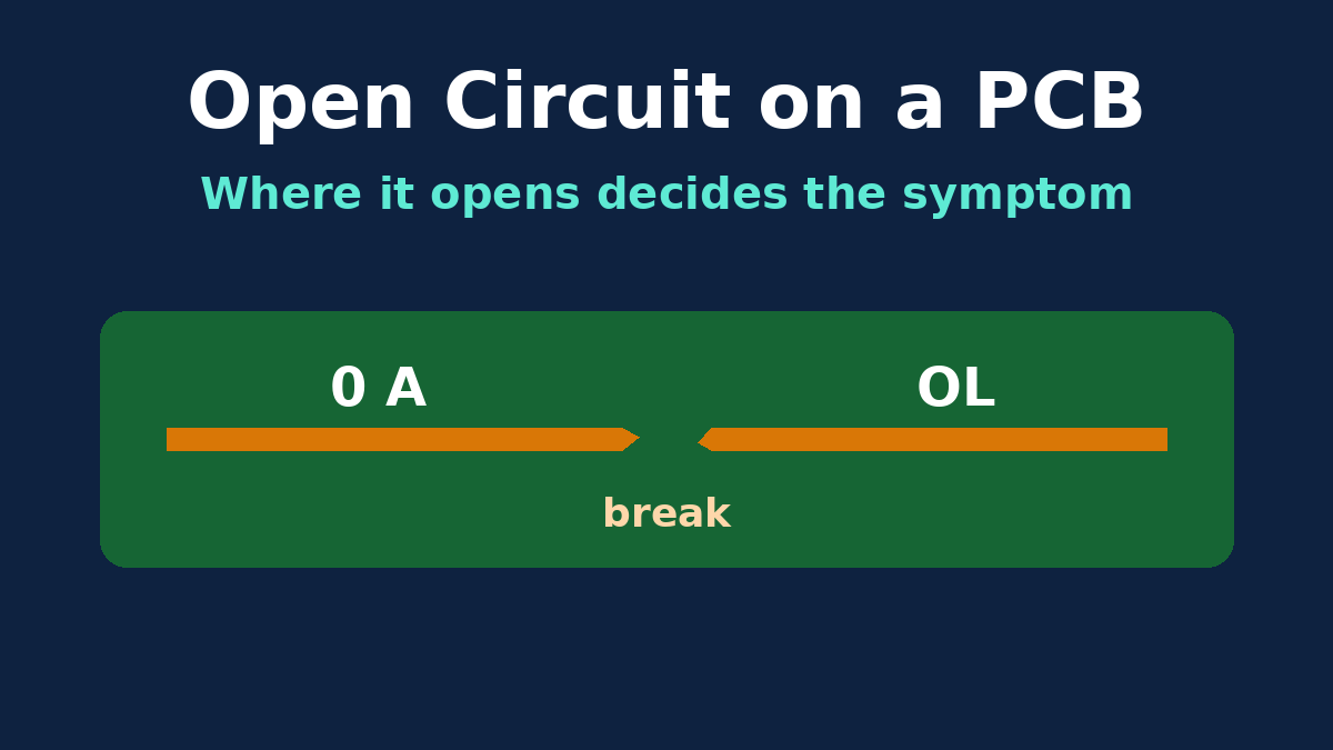
An open circuit is a break in a conducting path. The textbook summary is short: no current flows through the break, its resistance is effectively infinite, and voltage can still appear across it. All of that is true, and on a printed circuit board it's only the start. A board is hundreds of connected nets, and when one connection opens, the rest of the circuit keeps trying to work around it. Some opens make a board dead. Others leave it mostly working, sometimes in ways that are harder to diagnose than a dead board.
This guide explains open circuits in the terms a PCB team actually meets: what you measure at the break, why the symptom depends on which net opens, what floating nodes do, which opens are put there on purpose, and what "open" means when it appears on a factory test report.
What you measure at the break
Take a simple series loop on a board: a 5 V rail, a current-limiting resistor and an LED, connected by traces. As an illustration, with a 330 Ω resistor and an LED dropping about 2 V, roughly 9 mA flows: (5 V − 2 V) ÷ 330 Ω.
Now crack the trace between the resistor and the LED.
- Current through the loop drops to zero. There's no path, so nothing flows in any part of it, not just at the crack.
- Resistance across the crack, measured with the board unpowered, reads as an open, shown as "OL" on most meters.
- Voltage behaves less intuitively. With no current, the resistor drops no voltage, so both of its ends sit at 5 V. The LED's anode is no longer driven from the rail, so most of the 5 V now appears across the crack. (The meter itself pushes a tiny current through the LED, which still drops a little voltage at that current, so the reading can sit somewhat below 5 V.) A voltmeter placed across a break in a series path reads most or all of the source voltage.
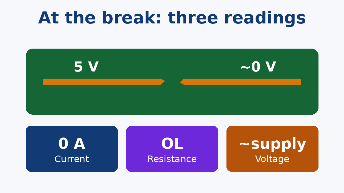
That last point is the most useful one at the bench. If you walk a meter along a dead series path with power applied, every point before the break reads the supply and points after it read near zero, or float. The break is where the reading changes.
A node with nothing driving it floats
When an open isolates part of a net, that part isn't at zero volts. It isn't at anything defined. A floating node takes whatever voltage stray capacitance, leakage and nearby signals give it, and a digital meter with a high input impedance can show a "ghost" reading there that disappears as soon as a load is applied.
This matters more on a board than in a lamp circuit, because what usually sits at the end of a broken trace is an IC input with very high impedance. A CMOS logic input that has lost its driver or its pull resistor can wander between high and low, pick up switching noise from neighbouring traces, and in some cases draw extra supply current while it sits near the switching threshold. An op-amp input that's lost its connection can drive the output to a rail. The board may pass a power-on check and then behave randomly.
The symptom depends on which net opens
The same physical defect, a cracked joint or a broken trace, produces very different results depending on what it disconnects.
| Where the open is | What the board tends to do |
|---|---|
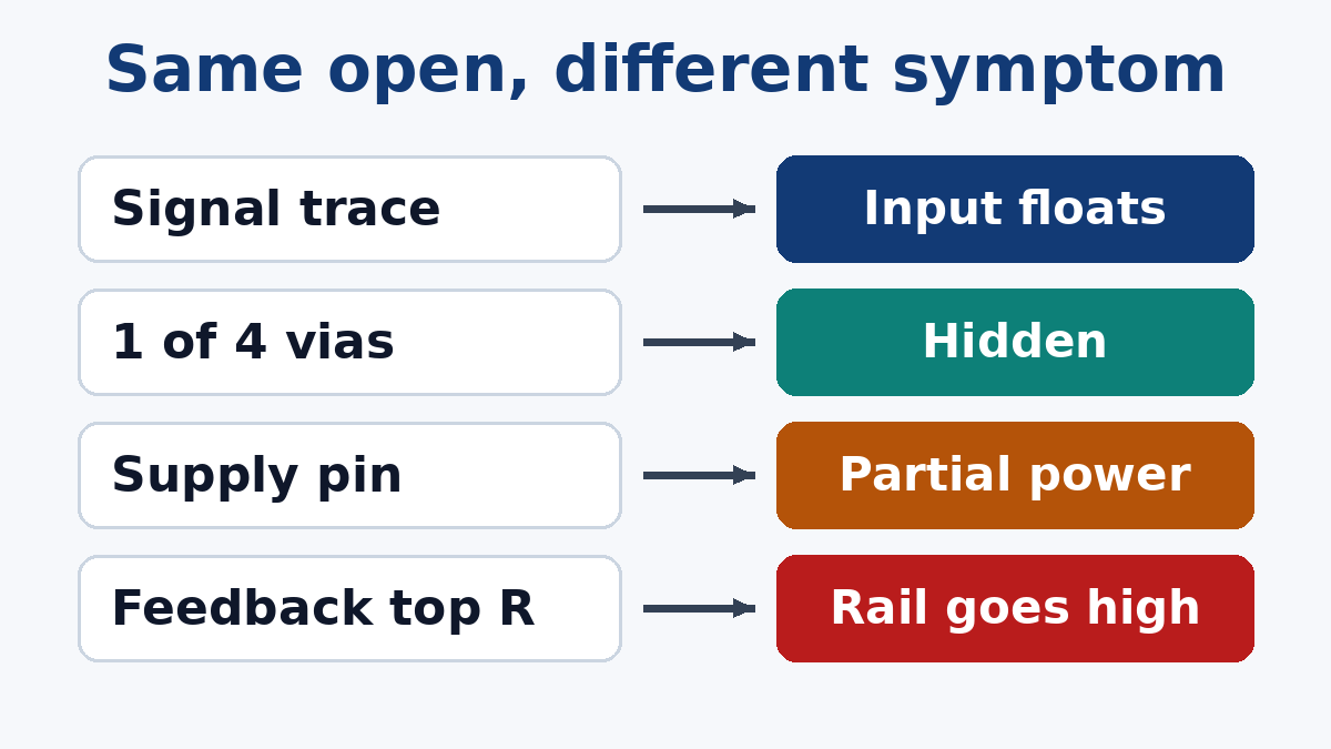
| A series signal trace | That function stops, or the receiving input floats and behaves erratically |
| An IC supply pin | The IC may partly power up through the internal protection diodes on its I/O pins, giving odd, partial behaviour |
| An IC ground pin | Return current finds another route, often through I/O pins and other devices' grounds; noisy or unstable operation |
| One of several parallel vias or pins | Often nothing visible; the remaining paths carry the current, with more heating and less margin |
| One leg of a decoupling capacitor | The board usually works on the bench but has more supply noise, which may show up only under load or in EMC testing |
| A pull-up or pull-down resistor | The signal floats; enables, resets and boot straps become unpredictable |
| A termination resistor | Fast signals ring and reflect; links may run with errors rather than fail outright |
| The top resistor of a regulator's feedback divider | The feedback pin sees too little voltage, so the regulator raises its output, potentially to its maximum |
| The bottom resistor of that divider | The feedback pin sees the full output, so the output regulates low |
The regulator rows are worth remembering. A single open in a feedback network can push a supply rail above what the parts it feeds are rated for. Designers who think about this sometimes arrange the feedback network, or add protection, so that the likely open fails low rather than high.
The parallel-path row is also important, because it explains why some opens survive testing. If a power connection uses four vias and one is open, the net is still continuous. A DC continuity check passes, and the board works. The open is real; it's just hidden by redundancy.
Not every open is a clean break
The textbook open is a gap with infinite resistance. Real ones aren't always that tidy:
- High-resistance connections. A joint with poor wetting, a thin or cracked plated barrel, or a partly broken trace may still conduct, but with much more resistance than intended. It passes a simple continuity beep and fails under current.
- Intermittent opens. A crack that closes when the board is cold and opens when it's warm, or one that moves with flexing or vibration, gives a board that fails in the field and passes on the bench.
- Opens that appear later. Thermal cycling, vibration and corrosion can turn a marginal connection into an open over time.
These are the opens that cause the most expensive investigations, and they're the reason factories combine several inspection and test methods rather than relying on one.
Opens that are there on purpose
Plenty of open circuits on a board are intentional, and it helps to make them obvious so nobody mistakes them for defects:
- Unpopulated (DNP) positions, where a resistor or zero-ohm link is left off to select an option.
- Solder jumpers that are open by default and closed with solder to change a configuration.
- Normally open switch and relay contacts, which are open until operated.
- Fuses, which are designed to open under fault current and protect the rest of the circuit.
"Open-drain" and "open-collector" outputs are a naming trap. They aren't faults; they're outputs that can pull a line low but rely on an external resistor to pull it high. If that pull-up is missing, though, the line floats, and you're back to an unintended open.
What "open" means on a test report
When a factory reports an open, it means something specific. In bare-board electrical test, the tester compares the board with the netlist from your design data. An open is two points that should be on the same net measuring above a set resistance threshold. A short is two points on different nets measuring below an isolation threshold. IPC-9252 sets out bare-board electrical test requirements, including how those thresholds are chosen for different performance classes.
On an assembled board, in-circuit and flying probe tests look for opens at component joints as well, and functional testing reveals opens that stop a function. Each method sees some opens and misses others; a single open via among four parallel ones, for example, generally needs a resistance-based or visual method to find. Our Testing & Inspection page outlines how electrical test, AOI, flying probe and X-ray are combined for bare boards and assemblies.
Design habits that make opens less harmful
A few choices during layout and schematic review make any open that does occur easier to live with:
- Give critical inputs a defined state. Enables, resets and mode pins with a pull resistor fail to a known condition instead of floating.
- Think about which way a feedback network fails. If an open would drive a rail high, consider protection or a different arrangement.
- Use more than one via for power and ground transitions, accepting that a continuity test won't notice if one of them is open.
- Provide test access on nets that matter, so opens can be found electrically rather than by guesswork.
- Mark intentional opens clearly in the BOM and assembly drawing, so DNP positions and open jumpers aren't "fixed" by someone downstream.
An open circuit is the simplest fault in electronics to define. On a real board, its effect depends on where it is and what the rest of the circuit does without it, and that is what makes it worth understanding properly.