
At the bench, the difference between an open circuit and a closed one usually comes down to a continuity test. Put the probes on two points, and the meter either beeps or it doesn't. On a bare wire that's all you need. On an assembled PCB, both answers can be wrong. A beep doesn't prove a good connection, and silence doesn't always prove a break.
This guide is about getting reliable open and closed answers from an assembled board: what the beep really means, the common false readings in each direction, and the better checks to use when a simple beep isn't enough.
Before any of it: power the board off and let the capacitors discharge. A continuity or resistance test pushes a small current from the meter into the circuit, and doing that on a live board gives meaningless readings and can damage the meter or the parts.
What a beep actually tells you
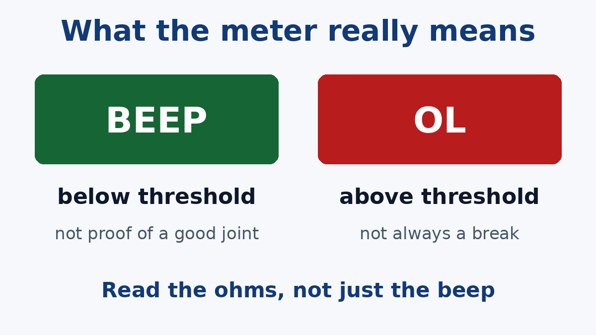
A meter in continuity mode measures resistance and beeps when it's below a threshold. The threshold varies by model; it's commonly a few tens of ohms, and the manual gives the exact figure. So a beep means "less than that many ohms between these two points by some path". It doesn't mean the path is the one you think, and it doesn't mean the connection can carry real current.
Likewise, no beep means "more than the threshold". The path might be fully open, or it might be a connection with more resistance than it should have, or the probes might not be touching copper at all.
Keeping those definitions in mind makes the false readings easier to spot.
False "closed": the meter beeps but the connection is bad
Another path completes the circuit. On an assembled board, two points are rarely connected by just one trace. If you check a trace between a resistor and an IC pin, the meter may also see a route through other components on the same net. A broken trace can beep happily because current flows around it.
Low-value parts look like wire. Inductors, ferrite beads, current-sense resistors and zero-ohm links all have resistance below a typical beep threshold. Across any of them the meter reports closed, which is correct electrically, but it can make a supply rail look shorted to another net when it's only connected through a filter.
Capacitors give a brief beep. Probe a supply rail against ground and the meter may beep for a moment while it charges the decoupling capacitors, then go quiet. That isn't a short. A steady beep is what matters.
One good path hides a bad one. If a connection uses several vias or several pins in parallel, one open among them doesn't change the beep. The same goes for a joint that's cracked but still touching. Continuity passes; the connection has lost margin.
High resistance below the threshold. A joint that measures a few ohms instead of a fraction of an ohm still beeps. For a signal line that may not matter. For a power path carrying an amp or more, it means heat and voltage drop.
False "open": silence that isn't a break
The probe isn't on copper. Solder mask, conformal coating, no-clean flux residue and oxidised pads all insulate. A probe on the mask beside a pad reads open. Probe the pad, a component lead or a test point, and press firmly enough to get through residue.
The wrong pad. On dense boards it's easy to land on a neighbouring pad, a via that belongs to another net, or a pad for an unpopulated position that's intentionally open.
It's only open some of the time. A cracked joint or barrel may be closed when the board is cool and open when it's warm, or the reverse. A single reading at room temperature catches one state.
Contacts that need current. Some switch and relay contacts are intended to carry more current than a meter supplies, and can show higher or unstable resistance at the meter's tiny test current. If a contact is supposed to be closed and reads erratically, check it at a realistic current before declaring it failed.
Better checks when the beep isn't enough
Read the resistance, not just the beep
Switch to resistance mode and note the value. For a direct trace connection, compare it with what the trace should measure. As an illustration: a 1 oz copper trace (about 35 µm thick), 0.2 mm wide and 50 mm long has a resistance of roughly 0.12 Ω (copper resistivity 1.72 × 10⁻⁸ Ω·m × 0.05 m ÷ (0.2 mm × 35 µm)).
That's smaller than the resistance of many meter leads and probe contacts. To measure at this level, touch the probes together and use the meter's relative or zero function to subtract the lead resistance, or use a four-wire (Kelvin) milliohm meter, which removes the leads from the measurement altogether. Low-ohm measurement is how you find the high-resistance joints and partial opens that a beep passes.
Use diode mode to check hidden IC joints
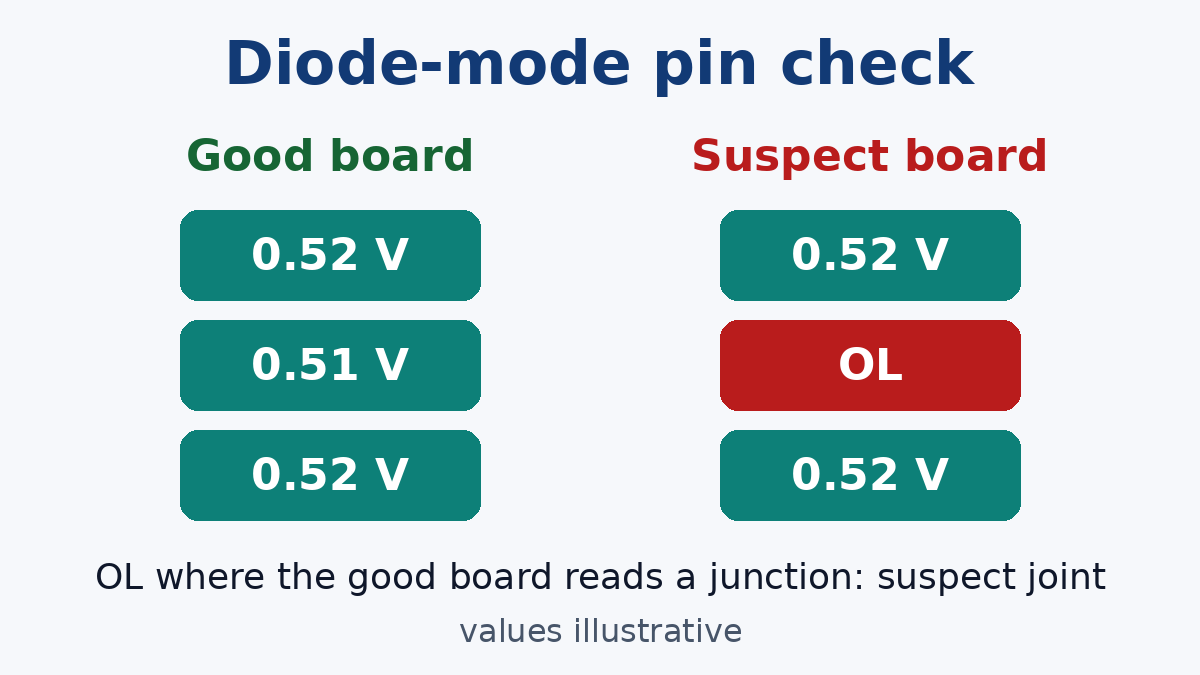
Most IC pins have internal protection diodes to the supply and ground. In diode mode, with the red probe on ground and the black probe on a pin, a connected pin usually shows a junction reading of a few hundred millivolts. A pin whose solder joint is open shows OL, because the meter can't reach the die.
This is one of the most useful checks for joints you can't see, such as BGA balls and the terminations under QFNs, as long as you probe from a point electrically connected to the pin (a trace, via or nearby component). Readings vary with what else sits on each net, so the most reliable method is to compare pin by pin against a known-good board of the same design. A pin reading OL on the suspect board where the good board shows a junction is a strong lead.
Compare with a known-good board
For any measurement, a good board from the same build is the best reference. Readings that look odd in isolation, such as a few kilohms between two pins, often turn out to be normal when the good board shows the same thing. Readings that differ point straight to the area to investigate.
Measure at the pin when the board is powered
If the board can be powered safely, measure supply voltage at the IC pin itself, not at the nearest capacitor. A rail that's present on the capacitor and missing on the pin points to an open between them, usually the joint.
Catching intermittent opens
Intermittent opens are the hardest to find because they're closed whenever you look. A few approaches help:
- Monitor while stressing. Leave the meter connected (or use its min/max capture) and gently flex the board, press near the suspect area, or tap with a plastic tool. A reading that jumps marks the region.
- Change the temperature. Warm the area with hot air at a moderate setting, or cool it with freeze spray, while watching the reading or the circuit's behaviour. Heat-sensitive opens often appear at a repeatable temperature.
- Record the conditions. Note which area, which direction of flex and which temperature trigger the fault. That information matters if the board goes for failure analysis.
Checking things that are meant to be open or closed
Not every open is a fault. Switches, relay contacts, solder jumpers and DNP positions are supposed to be open or closed in particular states. When verifying them, check both states: a normally open contact should read open at rest and closed when operated, and a normally closed one the reverse. A jumper that's supposed to be open but measures a few ohms may have a solder bridge or flux residue across it.
When to stop probing
Bench continuity testing is good for finding one fault on one board. It's less useful when:
- A whole lot is suspect. Flying Probe Testing checks each net for opens and shorts against the netlist, without a dedicated fixture.
- The suspect joint is hidden. When a diode check flags a BGA or QFN pin, X-Ray Inspection lets you look at the joint itself before anyone reworks it.
- The open is inside the board. If the trace and joints measure fine but the connection between layers doesn't, cross-sectioning by the factory is usually the way to find out what separated.
A short checklist
- Power off and discharge before measuring.
- Treat a beep as "below threshold", not "good".
- Probe copper, not mask or residue.
- Read the resistance and compare with what the path should be.
- Use relative mode or four-wire measurement for low ohms.
- Use diode mode and a known-good board for hidden IC joints.
- Stress and heat the area to catch intermittent opens.
Open versus closed is the simplest question in electronics. Getting a trustworthy answer on a populated board just takes knowing what the meter is really measuring.