
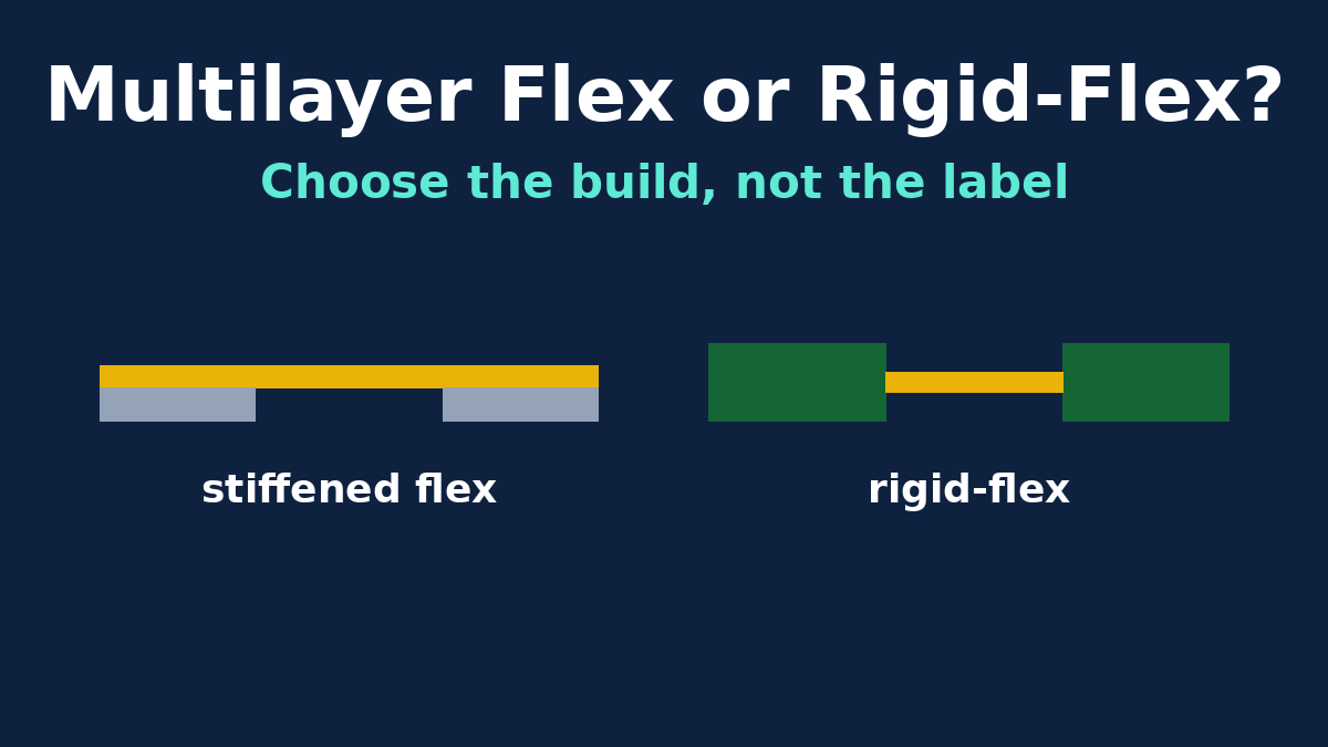
"Multilayer flex or rigid-flex?" sounds like a choice between two categories, but the terms overlap. Most rigid-flex boards contain a multilayer flex circuit, and a multilayer flex circuit with stiffeners bonded under its components can look a lot like a rigid-flex board on the bench. The useful question for a product team is more concrete. When a circuit has to fold into an enclosure, which of these do you actually build?
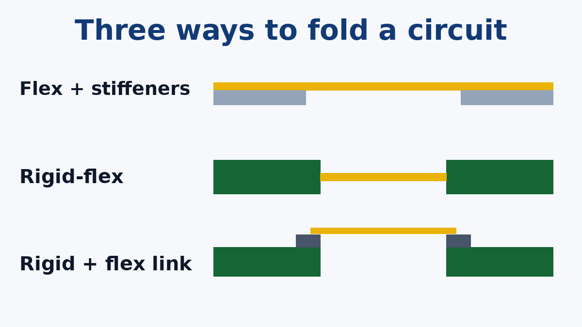
- A multilayer flex circuit with stiffeners bonded behind the component and connector areas.
- A true rigid-flex board, with rigid sections laminated into the same stack as the flex layers.
- Separate rigid boards joined by a flex circuit, connected with connectors or soldered joints.
This article compares those three builds on the factors that usually decide the question. Design rules for the bend itself, failure analysis at the rigid-to-flex transition and bookbinder constructions are covered in our other flex and rigid-flex articles. Here the focus is the choice of build.
What separates a stiffener from a rigid section
The difference that matters most is easy to miss when both boards are sitting on a desk.
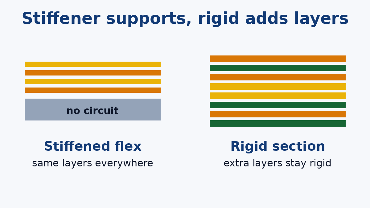
A stiffener is a mechanical part. It's a piece of FR-4, polyimide, stainless steel or aluminium bonded to the back of the flex circuit with adhesive, to support components or give a connector something firm to push against. It carries no circuitry. The circuit's layer count is the flex circuit's layer count, the same under the stiffener as everywhere else.
A rigid section in a rigid-flex board is part of the circuit. Rigid glass-epoxy layers are laminated onto the flex layers, and plated holes run through the whole stack. Crucially, the rigid section can carry more copper layers than the flex section. A rigid area might have eight layers, of which only two continue out into the flex.
In IPC-6013 terms, a multilayer flex circuit with plated through holes is Type 3, and a multilayer rigid-flex board with plated holes is Type 4. Using these type numbers on a quote request removes much of the ambiguity in the words.
Factor 1: Where you need the layers
This is usually the deciding factor.
Consider where the routing density is. On many products, the component areas are dense: a processor, memory, power circuits, many nets. But only a few dozen signals actually need to cross the fold.
With rigid-flex, the dense areas get as many layers as they need in the rigid sections, and only the signals that cross the fold go into the flex. The flex stays thin and flexible.
With multilayer flex and stiffeners, the component areas have only as many layers as the flex circuit itself. If those areas need six layers, the flex has six layers everywhere, including the bend, unless the layers are left unbonded through the bend region. More layers make a flex circuit stiffer and less tolerant of bending, so a high layer count driven by the component area works against the fold.
A simple test: if the layer count needed in the component areas is much higher than the layer count needed to cross the bend, rigid-flex is usually the better fit. If they're about the same and modest, multilayer flex with stiffeners is often enough.
Factor 2: What sits on the board
Fine-pitch BGAs and large ICs need a flat, stable surface through reflow and in use. A laminated rigid section provides that naturally. A stiffened flex can support them too, but flatness then depends on the stiffener, the adhesive and how the assembly is supported, which needs more care.
Through-hole and press-fit parts need plated holes in a rigid structure. Through-hole connectors can be fitted through a flex with a drilled stiffener behind it, but press-fit connectors need a rigid board.
Heavy parts and parts that take force, such as large connectors that are mated repeatedly, switches and battery holders, are better served by rigid sections.
Light surface-mount parts, ZIF tails and small connectors are well within what a stiffened flex circuit handles every day.
Factor 3: Mounting and mechanical fit
Rigid sections can be screwed to an enclosure like any board. A stiffener can carry mounting holes too, but it's held to the circuit by adhesive, so the joint between stiffener and flex becomes part of the mechanical design. Pressure-sensitive adhesive is quick and economical. Thermosetting adhesive gives a stronger, more temperature-resistant bond. If the stiffened area will be screwed down or carry load, tell the factory, because it affects the adhesive choice.
Thickness can tip the balance the other way. A stiffened flex circuit can be thinner and lighter in the component areas than a rigid section at normal board thickness, which matters in wearables and slim devices.
Factor 4: Where each build fails
Every build has a place where stress concentrates. Knowing where it is tells you what to protect.
Multilayer flex with stiffeners concentrates bending stress at the edge of the stiffener, where the circuit changes abruptly from supported to free. Traces and vias right at that edge, or a bend that starts at the edge, crack first. Common protections are keeping vias and pads back from the edge, running traces straight across it rather than at an angle, overlapping the coverlay under the stiffener edge, and sometimes a bead of flexible adhesive along the edge as strain relief.
Rigid-flex concentrates stress at the rigid-to-flex transition, where the flex layers leave the rigid laminate. The design rules for that zone (via setbacks, bend keep-outs and how the stack steps down) are the subject of our rigid-flex design guidelines article.
Rigid boards joined by flex move the risk to the joints: connectors that can loosen or fret under vibration, or soldered flex joints that need strain relief.
Factor 5: Fabrication and assembly
Rigid-flex is the more complex build. It combines flex processing (polyimide cores, coverlay, careful handling) with rigid multilayer processing, plus steps unique to rigid-flex: rigid material has to be kept off or removed from the flex regions, and plated holes in the rigid sections pass through a mix of glass-epoxy, polyimide and adhesive layers, which need hole preparation suited to that mix. More lamination and more steps generally mean higher cost and more process time than a comparable flex circuit with stiffeners. Our Rigid-Flex PCB page covers what we review on these builds before quoting.
Multilayer flex with stiffeners follows the flex process, with the stiffeners bonded on afterwards. Stiffener material, thickness, adhesive and position tolerances are the extra items to specify. Our Flexible PCB Capability page covers the coverlay and stiffener points we confirm before quoting.
For assembly, both need attention. Polyimide absorbs moisture, so flex and rigid-flex circuits are normally baked before reflow to avoid delamination. A flex circuit usually needs a carrier or fixture to hold it flat through printing, placement and reflow, with stiffeners helping locally. A rigid-flex board in a panel with a rigid frame handles more like a rigid board on the line, although its flex regions still need protecting.
The third option: rigid boards joined by a flex
It's easy to overlook the simplest build: two or more ordinary rigid boards connected by a flex circuit (or flat cable) with connectors, or soldered on by hot-bar or similar methods.
Its advantages are real. Each rigid board is a standard, inexpensive build. Any one of them can be redesigned without touching the others, and boards can be replaced in service. It's often the right choice while a design is still changing, at low volumes, or when only a handful of signals connect the boards.
The costs are the connectors themselves, the space they take, an extra assembly step, and the reliability of the connection under vibration and repeated movement. As volumes grow and the design settles, many products move from this build to rigid-flex to remove the connectors.
A short decision guide
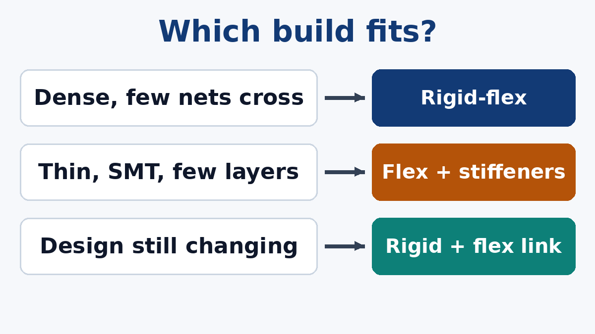
- Dense component areas, few signals across the fold, BGAs, press-fit or screw mounting: rigid-flex.
- Moderate density, surface-mount parts, thin or light product, similar layer needs everywhere: multilayer flex with stiffeners.
- Design still changing, few interconnecting signals, serviceability matters, or low volume: rigid boards joined by flex.
What to put on the quote request
- The build type, with the IPC-6013 type number.
- A stackup for each zone: layers in each rigid or stiffened area, layers in each flex region, and whether flex layers are bonded or unbonded through the bend.
- For stiffeners: material, thickness, adhesive type and position, and whether they carry mounting loads.
- The bend definition: bend radius, angle, and whether it's bent once at installation or flexes repeatedly in use.
- Which components sit on stiffened or rigid areas, including any BGAs or through-hole parts.
- How the circuits will be panelised for assembly, if we're also assembling them.
If you can't decide between two of these builds, send the outline, the component placement and the signals that cross the fold. Seeing those three things together usually makes the choice obvious, and quoting both builds is a straightforward way to compare cost.