
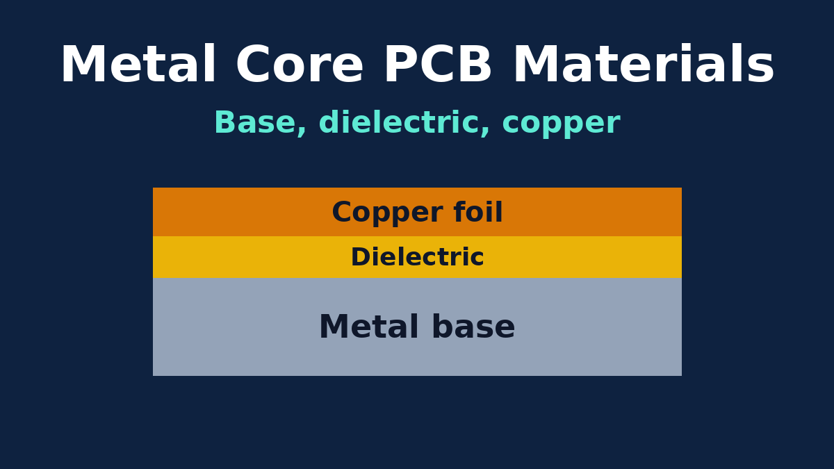
A metal core PCB is three materials stacked together: a copper foil for the circuit, a thin thermal dielectric, and a metal base. Most of the selection advice you'll find boils down to "pick a dielectric with a high W/m·K and use aluminium unless you need copper". That's not wrong, but it leaves out most of the choices that decide whether a board machines cleanly, survives thermal cycling, passes its hi-pot test and can be bought again next year without a surprise substitution.
This article takes each layer in turn and looks at what actually differs between the options, from the point of view of the factory that has to process them. The heat-flow arithmetic is covered in our metal core thermal path article, and which products need a metal core at all is covered in the applications article. Here the question is narrower: once you've decided on a metal core board, which materials do you write on the drawing, and how precisely?
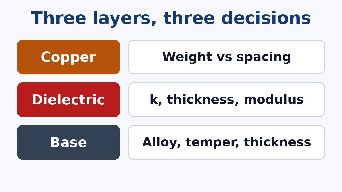
The base metal: choose it for mechanics as much as heat
It's natural to rank base metals by thermal conductivity. In practice, once heat has crossed the dielectric, the base spreads it so easily that its conductivity rarely limits the design. The base decides other things: how the board machines, whether it can be bent or formed, how stiff and heavy it is, and how it expands.
Aluminium grades
Aluminium is the default base, and "aluminium" covers several grades that behave differently on the production line.
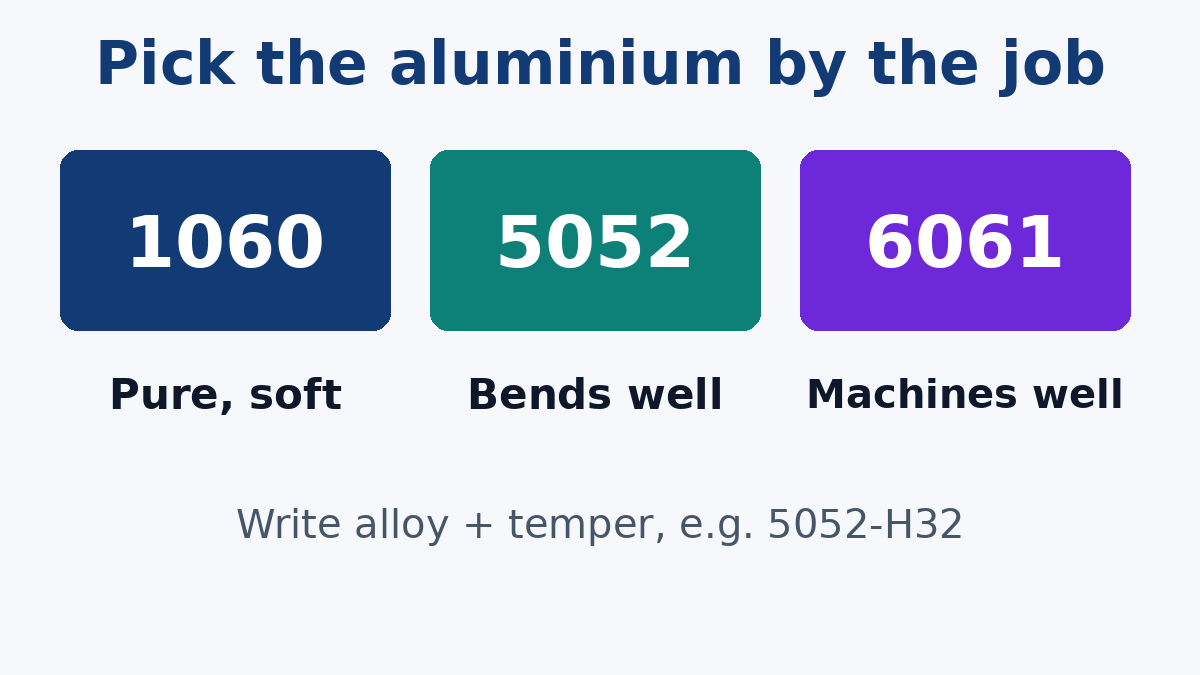
- 1050 and 1060 (commercially pure). These conduct heat best among common aluminium choices, but they're soft. Soft metal tends to smear rather than cut cleanly, so drilling and routing are more likely to leave burrs, and the boards dent more easily in handling.
- 5052 (aluminium-magnesium). A work-hardened alloy, supplied in tempers such as H32 or H34. It's stronger than pure aluminium, has good corrosion resistance, and bends well, which is why it's a common general-purpose choice for metal core laminate and the obvious pick if the board is formed or bent after fabrication.
- 6061 (aluminium-magnesium-silicon). A heat-treatable alloy, usually supplied as T6. It's stronger again and machines cleanly, which helps with countersunk holes, tapped holes, tight outlines and V-scoring. It's less forgiving if the board must be bent.
The alloys conduct noticeably less heat than the pure grades, but as explained above, that difference usually has little effect on component temperature compared with the dielectric. A practical rule: if the board is bent or formed, lean towards 5052. If it has machined features or needs a stiff, clean edge, lean towards 6061. If neither applies, use whatever the laminate grade you want is readily available in, because availability is a real constraint (more on that below).
Temper matters as much as alloy. "5052" without a temper doesn't tell the factory how hard the metal is. If bending or machining matters, write the alloy and the temper together.
Copper base
A copper base spreads heat better than aluminium and expands less (closer to the copper circuit above it), so it's chosen when heat sources are small and intense, or when the base is used as part of a pedestal construction where the component sits directly on raised copper. The penalties are weight (copper is roughly three times as dense as aluminium), material cost, and machining: copper wears drills and router bits faster, and its surface oxidises, so the bare face needs protection or a finish. Pure copper grades such as C11000 are typical.
Steel and iron bases
Steel bases exist for niche uses, mostly where stiffness or magnetic properties are wanted. Their thermal conductivity is far lower than aluminium's, so they're not a thermal upgrade. If you're specifying one, it's a special build, and it's worth discussing it with the factory before design is finished.
Base thickness
Choose base thickness for the mechanical job: stiffness across the mounting points, the screw clamping force, total board height for connectors and housings, and weight. A thicker base doesn't fix a thermal problem caused by the dielectric or the heat sink interface. Thin bases on large boards are more prone to bow, which hurts heat sink contact, so on big boards the thicker option often earns its weight by staying flat.
Back surface
The metal side is usually supplied bare under a protective film, brushed, or anodised. Anodising gives a harder, more corrosion-resistant face and a consistent appearance. Don't treat it as electrical insulation unless it's specified and tested as such, and if the board's back must make good thermal contact, check that the chosen treatment works with your thermal interface material.
The dielectric: more than a conductivity number
The dielectric is where most of the material decision really sits, and it's where quotes most often differ without the buyer noticing. A dielectric is a resin system, usually epoxy-based, filled with ceramic particles to raise its thermal conductivity. Beyond that, products differ in ways that a single W/m·K figure doesn't show.
Reinforced or unreinforced. Some dielectrics include glass fabric, which makes the layer tougher and less prone to damage during punching and handling. Unreinforced, highly filled layers often reach higher conductivity. If your board is punched in volume or sees mechanical abuse, ask which kind you're getting.
Thickness and breakdown. Thinner is better thermally and worse electrically. The datasheet breakdown voltage is measured on laminate samples under the supplier's conditions. A finished board, with holes, edges and handling, has less margin than that. Specify the finished-board hi-pot requirement on the drawing, and let the dielectric thickness be chosen to meet it with margin, rather than assuming the datasheet number will carry over.
Stiffness (modulus). This is the property most often missed. Aluminium expands more than three times as much as ceramic component bodies when it heats up, and on a rigid dielectric that mismatch goes straight into the solder joints. Over many thermal cycles, joints on large ceramic packages can crack. Some dielectrics are formulated to be softer (low modulus) so that they absorb part of the strain. If your board carries large ceramic LEDs, ceramic capacitors or resistors and will see wide temperature swings, the dielectric's modulus deserves as much attention as its conductivity.
Temperature rating. Look at the glass transition temperature and, for safety-certified products, the laminate's UL listing: flammability rating and relative thermal index (RTI). The RTI is the temperature the material is rated to run at long-term, and certification bodies often check it.
Tracking resistance. If your product's safety standard sizes creepage distances by material group, the comparative tracking index (CTI, tested to IEC 60112) of the materials on the circuit side becomes part of the electrical design, not just a datasheet line.
How conductivity was measured. Different test methods give different numbers for the same product. Our thermal path article explains why. When two quotes list different W/m·K values, check the method before comparing.
The copper foil
The circuit copper is usually electrodeposited foil bonded to the dielectric by the laminate maker. The decision is mostly copper weight. Heavier copper carries more current and spreads heat better before it reaches the dielectric, but it etches with more undercut, so spacing has to grow, and solder mask has to cover taller edges. If you need heavy copper on a metal core board, check fine-pitch areas against the spacing the copper weight allows, and confirm it with the factory early.
Not every dielectric is offered in every copper weight and base thickness. Laminates are made in specific combinations, and an unusual pairing (a particular high-performance dielectric on a thick 6061 base with heavy copper, say) may need a special order or may not exist. Checking availability before the layout is frozen saves a redesign.
Writing "or equivalent" so it means something
Most drawings name a dielectric "or equivalent". That's sensible, because it lets the factory use a material it stocks, but only if "equivalent" is defined. Without a definition, a quote can be cheaper because a different, lower-performing material was assumed.
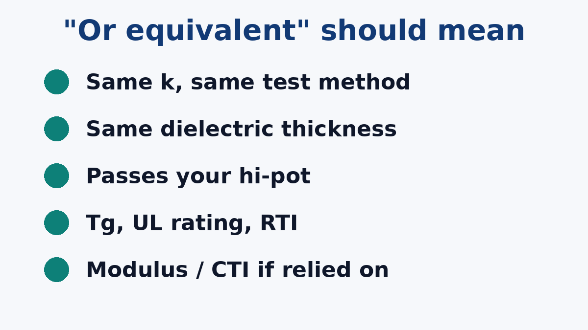
A workable definition of equivalence lists the properties you actually rely on:
- Thermal conductivity at or above your value, measured by the same method.
- The same dielectric thickness, within a stated tolerance.
- Finished-board hi-pot to your stated conditions.
- Glass transition temperature, flammability rating and RTI at or above your values.
- Low-modulus behaviour, if your reliability depends on it.
- CTI group, if your creepage design depends on it.
- The base alloy, temper and thickness, and the copper weight.
Add a line that any substitution needs written approval before production. That one sentence prevents most material surprises.
A material callout template
Here's a structure for the material notes on a metal core drawing. The values are placeholders to be filled from your own design, not recommendations:
- Base: aluminium [alloy]-[temper], [thickness] mm, back surface [bare / brushed / anodised].
- Dielectric: [grade] or approved equivalent; thermal conductivity ≥ [value] W/m·K per [test method]; thickness [value] µm ± [tolerance]; Tg ≥ [value]; flammability [rating].
- Copper: [weight] finished on circuit layer.
- Hi-pot: [AC/DC] [voltage] for [time], leakage ≤ [limit], [100% / sample].
- Substitution: no material substitution without written approval.
Where our team comes in
During review, we check the materials called out against what's available in the combinations requested, and we flag pairings that will be hard to source or process. Our PCB Materials guide compares metal core laminates with FR-4, high Tg, RF and flex materials, and standard aluminium builds are described on our Aluminum PCB page. If your drawing leaves a material property open, we'll ask about it rather than choose for you.