
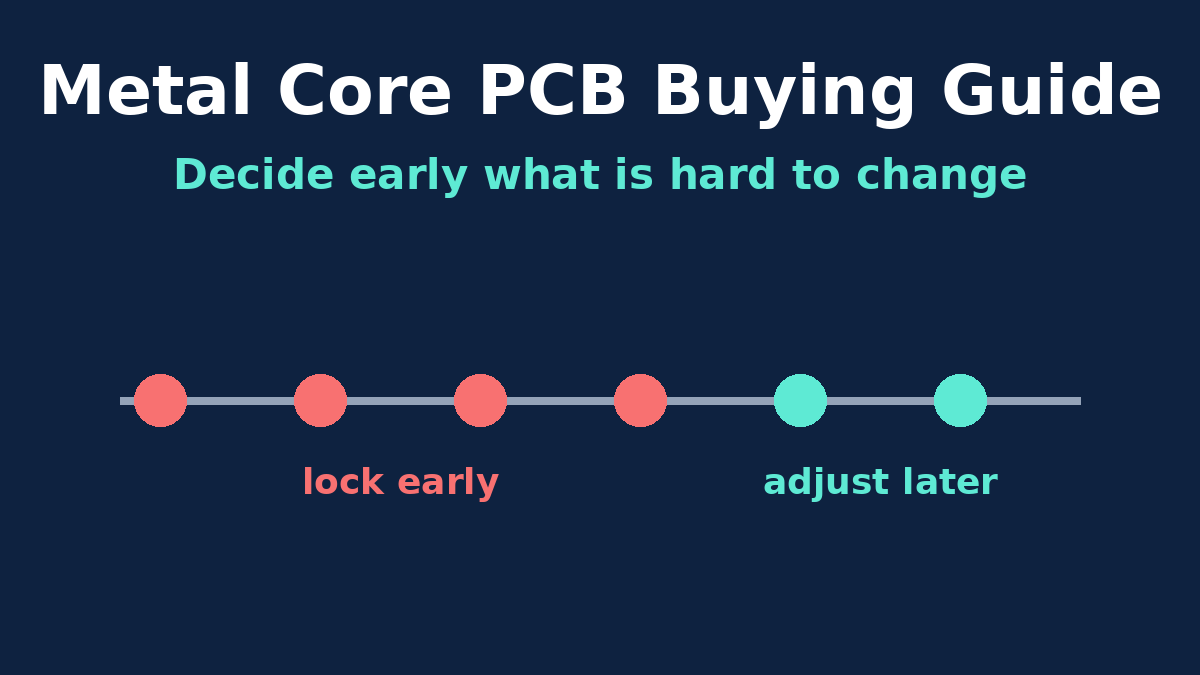
A metal core PCB looks like one of the simplest boards you can buy: often a single copper layer on a sheet of aluminium. The project around it is less simple. Several decisions get made early, sometimes without anyone noticing they were decisions, and changing them later means a new layout, new tooling, a new certification test or a new round of thermal measurements.
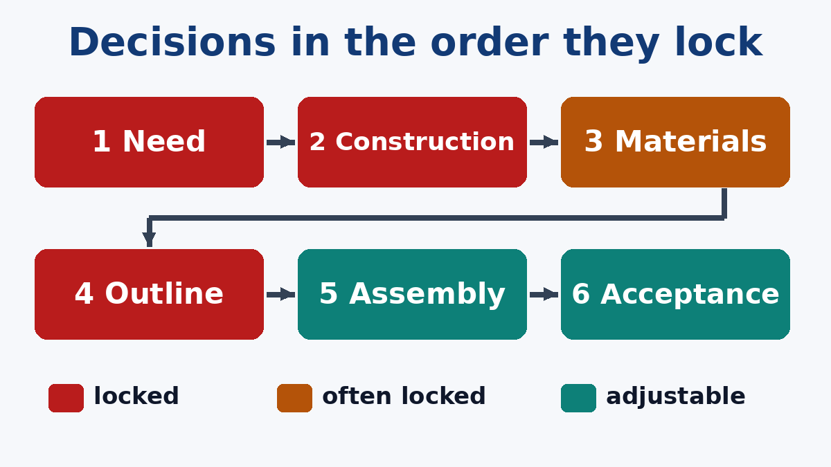
This overview is for buyers and engineers sourcing metal core boards. It goes through the decisions roughly in the order a project meets them and flags which ones are cheap to revisit and which are not. The detailed engineering behind each one is covered in our other metal core articles on applications, thermal paths, materials, constructions and the fabrication process. This article is about sequence, cost and consistency from prototype to production.
1. Confirm a metal core is the right tool
The first decision is whether you need one at all. A metal core board earns its place when a few parts dissipate enough heat that a normal board, even with copper pours, thermal vias and a heat sink, can't keep them inside their temperature limits. If a simple thermal budget shows FR-4 with a heat sink already works, a metal core adds cost and design restrictions for nothing.
Also consider whether the whole circuit needs to be on metal. Many products put only the LEDs or power devices on a small metal core board and keep the control electronics on FR-4. That split is easy to decide at the start and painful to introduce after the layout is done.
Hard to change later? Yes. Moving between FR-4 and metal core, or splitting one board into two, is a redesign.
2. Choose the construction before layout starts
Single-layer, two layers on one side, a double-sided board with the core in the middle, a multilayer bonded to metal, a copper pedestal build: each has its own design rules, process route and price level. The construction decides whether through-hole parts are possible, whether components can go on both sides, and whether a hot part's thermal pad can touch the metal directly.
The construction is the single biggest driver of cost and of which factories can quote. Settle it before layout, and put it in writing on the drawing so that every quote is for the same thing.
Hard to change later? Yes. A change of construction means re-layout.
3. Lock the materials, and know what they're tied to
The dielectric (its grade, thermal conductivity and thickness), the base metal and its thickness, and the copper weight are usually chosen together. Two links make this decision stickier than it looks.
First, the dielectric thickness is tied to the insulation requirement. If the product has to pass a hi-pot or safety test between circuit and base, the dielectric was chosen to meet it, and a thinner, "better" thermal material may not.
Second, if the product is safety certified, the certification file may list the laminate. Changing it later can mean asking the certification body whether re-evaluation is needed. Check this with whoever manages your certification before you treat a material change as a simple cost-down.
There's also a softer link: the thermal measurements you made on prototypes are only valid for the materials those prototypes were built with.
Hard to change later? Often. Cheap on paper, but it can reopen thermal validation and certification.
4. Finalise the outline before any production tooling
Prototypes and small runs of metal core boards are normally routed. Larger volumes are often punched with hard tooling, which is fast and economical per board but means a one-off tool made to the outline. Once that tool exists, an outline change means a new tool.
The cutting method also changes the edge. A punched edge and a routed edge aren't identical, and metal core boards are sensitive to edge burrs and dielectric damage near the outline. If production will be punched, it's worth building a pilot lot with the production method and re-running the hi-pot and edge inspection on those boards, rather than assuming the routed prototypes represent production.
Panel format belongs in the same decision. V-scored metal panels are snapped or cut apart at assembly, which stresses the edge. Tab-routed panels cost more panel area but separate more gently. Agree the format with both the board maker and the assembler.
Hard to change later? Yes, once tooling is made.
5. Plan assembly and mounting with the real board
A metal core board behaves differently on an assembly line. The metal pulls heat away from the pads, so the reflow profile has to be developed on the actual board, not copied from an FR-4 job. Hand soldering and rework are harder for the same reason. A preheat plate under the board is usually needed, and wires or large connectors soldered directly to big copper pads take longer to wet than they would on FR-4. If the design has wire pads, consider whether a connector or a different termination would make assembly more repeatable.
Mounting is part of the design too. The way the board is screwed or clamped to the heat sink, the thermal interface material and the screw torque all affect both temperature and stress on the dielectric. These belong in the assembly or mechanical documentation, not left to whoever builds the product.
Two smaller points buyers often miss:
- Packaging. Bare aluminium faces scratch and dent easily in transit. If the metal face is visible or must stay flat for heat sink contact, ask for interleaved packaging.
- White solder mask colour. On LED boards the mask's whiteness matters optically, and repeated heating can discolour some masks. If colour stability matters, say so.
For LED products, our LED PCB Assembly page lists the controls we apply specifically to LED boards.
Hard to change later? Mostly no, but late discoveries here delay first shipments.
6. Write the acceptance criteria down
Metal core boards have a few acceptance points that standard boards don't, and if they aren't written down, each factory applies its own default:
- Hi-pot conditions: voltage, AC or DC, dwell time, leakage limit and whether every board is tested.
- Metal-side appearance: what scratches, rub marks or discolouration are acceptable, if the back is visible.
- Flatness: if the board is clamped to a heat sink.
- Thermal verification on first articles: a simple temperature check at known power, compared against the prototype result, catches a material or process change early.
Hard to change later? No, but adding criteria after production starts often means arguing over parts already made.
Where the cost actually comes from
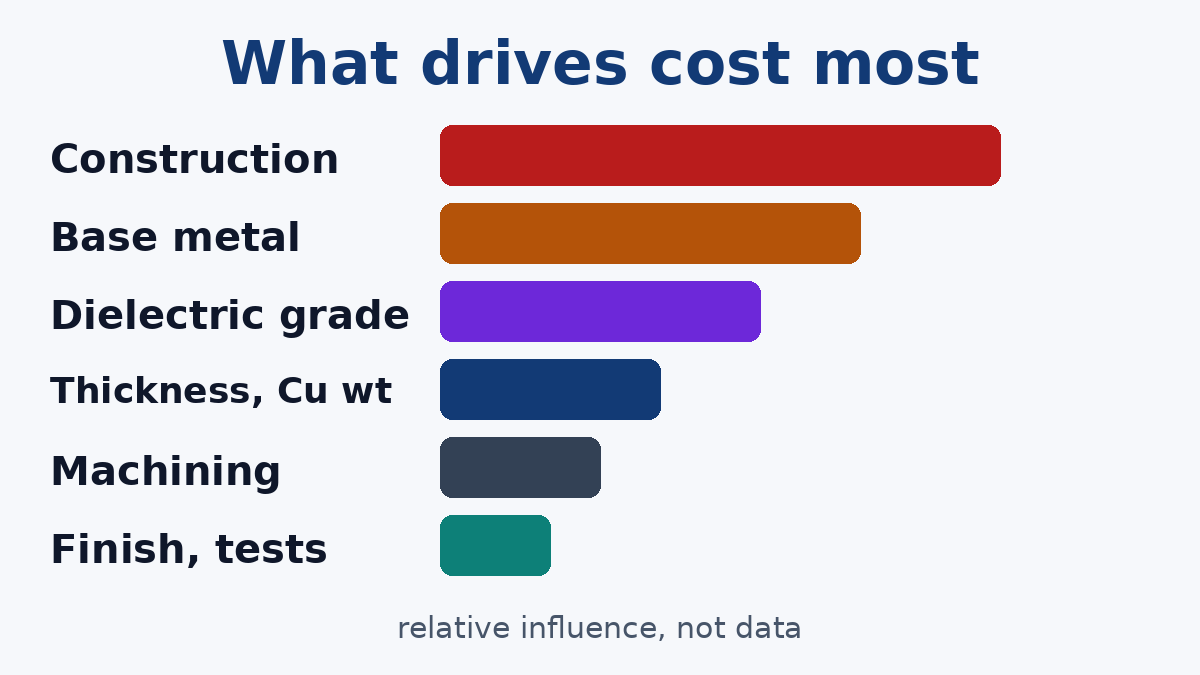
Without quoting figures, which depend on size, volume and the market at the time, the drivers of metal core board cost can be ranked by influence fairly reliably:
- Construction. A double-sided core, multilayer on metal or pedestal build is a different class of product from a single-layer board.
- Base metal. Copper costs much more than aluminium to buy and to machine.
- Dielectric grade. Higher-conductivity grades cost more, and unusual grades may carry minimum order quantities.
- Non-standard thicknesses and copper weights, which may need special material.
- Machining features such as countersinks, steps and cut-outs.
- Finish, mask colour and test scope.
Real savings usually come from the top of the list: a simpler construction, aluminium instead of copper after improving copper spreading on the circuit layer, or a standard dielectric when the thermal budget allows it. Savings from the bottom of the list are small, and dropping tests that protect safety isn't a saving at all.
7. Move to production without changing the board by accident
The most common prototype-to-production problem with metal core boards isn't a defect. It's a quiet difference: prototypes built on whatever dielectric was in stock, production built on another, both "2 W/m·K". Or prototypes routed and production punched. The boards look the same and measure differently.
A few habits prevent it:
- Build PCB Prototype lots with the exact material callout intended for production, not a placeholder.
- Name the dielectric grade or define "equivalent" precisely, and require written approval for substitutions.
- Run a pilot lot with production tooling and the production panel, and repeat the hi-pot and thermal checks on it.
- Keep the first article results as the reference that later lots are compared against.
When an order moves into PCB Mass Production with us, these points are part of what we confirm with the customer before the first volume lot, because they're far cheaper to settle then than to investigate after a field complaint.
A short checklist for the RFQ
- Construction, stated plainly, with a stack sketch.
- Dielectric grade or full equivalence definition, base metal, thicknesses and copper weight.
- Hi-pot conditions and any safety certification constraints on materials.
- Outline method expectations and panel format.
- Metal-side appearance, flatness and packaging requirements.
- Expected volumes, so tooling and material choices are made with production in mind.
With those in hand, quotes from different suppliers become comparable, and the board you approve at prototype stage is the board you keep receiving.