
Most writing about design for manufacturability is aimed at the designer: rules for trace width, annular ring, solder mask dams and component spacing. Those rules matter, but they describe only half of DFM. The other half happens after the files leave your hands, when a factory engineer opens them and decides whether, and how, the board can be built as drawn.
That review is where the questions come from, where most of the "why is my order on hold?" moments begin, and where several decisions about your board are made on your behalf. Understanding how it runs makes it easier to send data that passes quickly and to answer questions in a way that does not create a second round.
This is how a DFM review runs at our factory in Shenzhen, from the moment the files arrive to the point the job is released to production. Other factories differ in details, but the stages are broadly the same.
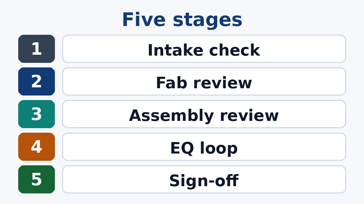
Stage 1: Intake and completeness
Before anyone looks at manufacturability, the package is checked for completeness and consistency. Are all copper layers, solder mask, legend, drill and outline files present? Is there a drawing or notes file with material, thickness, copper weight, finish and any special requirements? For assembly, is there a BOM and a placement file, and do they refer to the same revision as the Gerbers?
Problems found here are the cheapest to fix and the most frustrating to have: a missing drill file or two different revision letters in the same package can stop the job before any engineering starts.
Stage 2: Fabrication review
The CAM engineer loads the data and checks it against the factory's process capability for the stated material and class. Typical areas:
- Stackup. Does the requested thickness work with available cores and prepregs? Do impedance targets fit the stackup, and which geometry changes would be needed?
- Drilling. Hole sizes, aspect ratio, annular ring after drill tolerance, via structures (blind, buried, filled), slots and their tolerances.
- Copper. Minimum line and space for the copper weight, copper to board edge, isolated copper, copper balance between layers.
- Solder mask and legend. Mask dams between fine-pitch pads, mask over vias (tented, plugged, filled), legend on pads.
- Outline and panel. Board outline, internal cut-outs, routing and scoring, and how the board will be panelised for fabrication.
The result is not a pass or fail. It is a list of items, each of which falls into one of the categories described below.
Stage 3: Assembly review
For PCBA orders, a second review looks at the board through the assembly process:
- BOM against footprints. Does each part's package match the pad pattern? This is where a SOT-23 footprint with a part that ships in SOT-23-5, or a capacitor ordered in the wrong case size, is caught.
- Polarity and orientation. Are pin 1 marks, diode bands and polarised capacitor markings consistent between the legend, the placement file and the BOM?
- Spacing and access. Clearance between parts for placement, inspection and rework; tall parts that shadow smaller ones; parts too close to the board edge or to depaneling lines.
- Process route. Which side is reflowed first, whether any heavy parts need glue on the second side, which through-hole parts need wave, selective or hand soldering.
- Stencil. Aperture modifications for fine-pitch parts, thermal pads and through-hole pin-in-paste.
- Test. Test point access for flying probe or fixture testing, and any functional test requirements.
What gets adjusted silently, and what does not
A factory makes many adjustments to your data as a matter of routine. These are not design changes; they are compensations for the process, and you would not normally be asked about them:
- Etch compensation of trace widths, so the finished width matches the design
- Drill size selection to give the specified finished hole size after plating
- Solder mask opening adjustments within the factory's standard clearance
- Adding copper thieving in empty areas outside the board to balance plating, where it does not touch the circuit
- Panel rails, fiducials and tooling holes on the production panel
What a factory should not change without asking is anything that alters the design's function, appearance or fit: trace widths beyond normal compensation, impedance geometry, hole sizes outside their tolerance, the board outline, copper inside the board, legend content, or the parts on the BOM. If your design has areas where even standard adjustments are not acceptable, such as RF structures, precise etched features or copper you do not want thieved, say so on the drawing.
Classifying findings
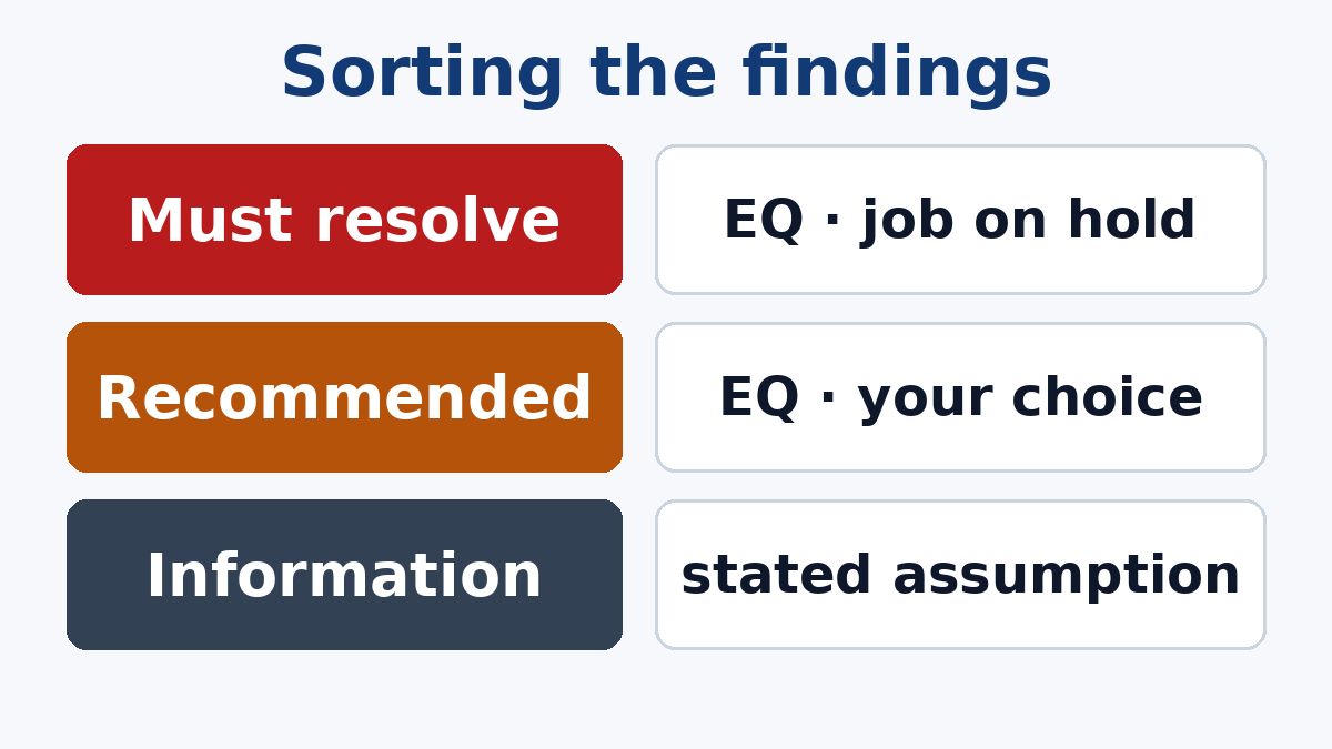
Each finding from the review is sorted:
- Must resolve. The board cannot be built as drawn, or will fail a basic requirement: an annular ring that disappears after drilling, a footprint that does not match the part, conflicting thickness and stackup requirements.
- Recommended. It can be built, but with lower yield, higher cost or a known reliability risk: mask dams that will likely break, a via in a pad without fill, a part sitting on a scoring line.
- Information. The factory will proceed with a stated assumption: a default finish because none was specified, an impedance tolerance taken from the standard because the drawing did not state one.
The first two become engineering queries (EQs). Information items are often listed in the same document so that the assumptions are visible.
The EQ loop
An EQ should be easy to answer. A good one states the finding, shows exactly where it is with an image or coordinates, explains why it matters, and proposes one or more solutions, for example: "Annular ring on these vias is below the minimum after drill tolerance. Option A: increase pad to the size shown. Option B: reduce drill size to the size shown; finished hole will be smaller. Please confirm A or B."
From the buyer's side, a few habits keep the loop short:
- Answer every item explicitly, even when the answer is "accept your proposal".
- Say whether the answer applies to the whole board. "Yes, apply to all similar vias" prevents three more questions.
- Update the source data if the change is permanent. Otherwise the same EQ appears on the next order.
- Do not send a new revision in reply to a single EQ unless you intend the factory to restart the review on the new data.
Most jobs need one round. A second round usually means a new question raised by the answer to the first, or a new revision that changed something else.
Sign-off
Once the EQs are closed, the job is ready for release. For simple boards, release follows directly. For complex, high-value or first-time boards, a formal approval step is worthwhile:
- Working Gerber or production data approval: you see the final data the factory will build from, including compensations and panelisation, and approve it.
- Stackup and impedance approval: for controlled-impedance boards, the proposed stackup and line widths are confirmed before materials are cut.
- Panel drawing approval: for assembly panels, the array, rails, fiducials and break-off method are confirmed.
Approval adds a short wait, but it moves the last chance to catch a problem from the finished boards to the screen. The PCB Fabrication Process page describes what happens to the board after this point.
On repeat orders
For an unchanged repeat order, the factory reuses the approved production data and the review is limited to confirming that nothing has changed. That is why it pays to keep revision letters disciplined. A package that looks identical but carries a different revision, or a "minor" change that was not flagged, sends the job back through the full review.
How to make your next review faster
- Send a complete, consistent package, with the drawing stating material, thickness, copper, finish, class and special requirements. Our Manufacturing Files page lists what we need.
- Mark areas where routine compensation or thieving is not acceptable.
- Give approved alternates and substitution rules on the BOM.
- Name one person to answer EQs, and answer them in one reply.
- Ask for production data approval on complex or first-time boards.
If you would like to see what a DFM review of your board would raise before you place an order, send us the files. Our engineers can return the findings and proposals so you can decide what to change in the design and what to accept.