
A fab-ready Gerber package is the manufacturing data set CAM opens after your CAD green-check — not the layout file itself. Prefer RS-274X (Extended Gerber) with embedded apertures; skip legacy RS-274D aperture wheels. Gerber X2 / X3 attributes help layer identity when both sides support them, but a plain RS-274X zip plus a layer-map README still clears most China fab gates. This note is the outline gate: what belongs in the package, why GKO / keep-out is a design constraint (not the milling outline), why the .GKO extension confuses, how a closed continuous single outline prevents CAM holds, and which viewer QC steps and RFQ questions cut EQ loops. It is not an EAGLE export tutorial and not a full fab-process walkthrough.
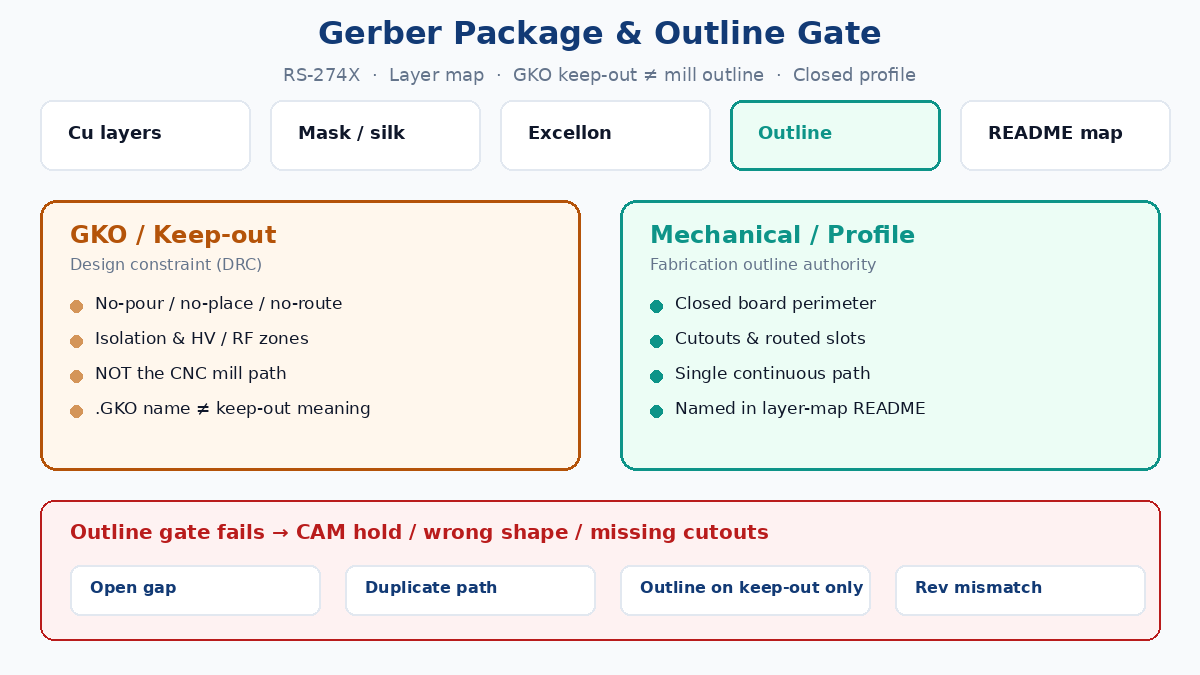
Quick answer: package vs outline authority
| Item | Owns | Does not own |
|---|---|---|
| RS-274X copper / mask / silk | Artwork for etch, mask, legend | Board perimeter for CNC route |
| Excellon / NC drill | Plated and non-plated hole locations/sizes | Outline path unless slots are explicitly defined as routed features |
| GKO / keep-out (CAD semantics) | No-pour, no-place, no-route, isolation zones for DRC | Authoritative board shape, cutouts, mill slots |
| Mechanical / profile / outline file | Closed board shape, internal cutouts, routed slots, fab geometry notes | Copper DRC keep-out rules |
| Layer-map README | Filename → layer meaning, outline file name, PTH vs NPTH | Stackup chemistry or price |
Put keep-out geometry on keep-out. Put the cut path on a mechanical, profile, or dedicated outline Gerber — and name that file in the README so CAM does not guess from an extension.
What a fab-ready Gerber package is
CAM does not open your .brd or project file as the contract. The contract is the exported zip: Gerbers + drill + notes that survive a different tool chain. Minimum content for a bare-board RFQ:
- Copper layers — top, bottom, and every inner in stack order (positive preferred unless the fab asks for plane negatives and you document polarity).
- Solder mask top and bottom (paste/stencil only if stencil or assembly is in scope).
- Silkscreen as required for assembly cues; omit blank silk rather than shipping empty files.
- Board outline / profile — one authoritative closed path for finished shape, plus cutouts and mill slots on the same mechanical family (or clearly mapped).
- Excellon (or NC) drill — plated through-holes and non-plated holes separated or charted; tool sizes and units matching Gerber units/origin.
- Fab notes — finish, mask color, IPC class callout, thickness, copper weight, special tolerances, impedance block if quoted.
- Layer map README — plain text: each filename, intended layer, which file is the outline, which drill is PTH vs NPTH, revision letter shared across the zip.
RS-274X embeds aperture definitions in each file. Do not ship RS-274D + separate aperture list unless the fab explicitly requires that legacy pair. X2/X3 file attributes (.gbr with layer function metadata) reduce mis-assignment when the receiver’s CAM reads them; if you export X2, still keep human-readable names and a README — attributes are help, not a substitute for a map when an uploader ignores them.
One revision letter or date stamp on every file in the zip. Mixing Rev B copper with Rev A outline is a classic wrong-shape scrap path.
Required layers, Excellon, and naming that survives China CAM
China fab uploaders and CAM desks see every naming habit: Protel-style extensions (.GTL, .GBL, .GTS, .GTO, .TXT), KiCad *-F_Cu.gbr, Altium Job-named .gbr, and random Layer1.gbr. None of those extensions are sacred in the RS-274X standard. What is sacred is unambiguous assignment.
Practical naming habits that cut holds:
- Prefer descriptive stems:
Project_RevC_Outline.gbr,Project_RevC_TopCopper.gbr,Project_RevC_PTH.drl,Project_RevC_NPTH.drl. - If you keep Protel extensions for habit, still attach
README_layer_map.txtthat says, in one line each, what.GKO/.GM1/.GMLmeans in this zip. - Do not put drawing frames, title blocks, or dimension text on the copper or outline file CAM will mill from. Put dimensions on a separate mechanical notes layer or a PDF fab drawing referenced in the README.
- Slots: either true routed slots on the outline/mechanical file, or drill slots clearly called out — never “looks like a slot on copper.”
Excellon must share unit and origin with the Gerbers. A uniform hole-pattern shift usually means inch/mm or origin mismatch, not “small CAD error.” Separate PTH and NPTH when the fab’s DFM expects it; if you merge tools, put a hole chart in the fab notes that marks plated vs non-plated.
Core gate: GKO keep-out ≠ milling outline
This is the failure mode that burns time on otherwise clean jobs.
Keep-out / GKO (CAD meaning) is a design-time constraint. It tells the layout engine and DRC where copper pours must stop, where components must not sit, where traces must not cross, and where high-voltage or RF clearance zones live. That geometry is for the designer. Manufacturers do not treat keep-out as the CNC route path.
Mechanical / profile / outline is the fabrication instruction. It carries:
- Finished board perimeter (closed path)
- Internal cutouts and windows
- Routed slots and mill features that define shape
- Optional tooling/fiducial notes when you put them on a mechanical layer the README identifies
| Intent | Correct home | Wrong home |
|---|---|---|
| No copper / no place / no route zone | Keep-out (GKO) | Outline file CAM will mill |
| Board shape | Mechanical / Profile / Outline | Keep-out only |
| Internal cutout / mill pocket | Mechanical / Outline | Silk, mask, or bare keep-out |
| Dimension / fab callout text | Separate mechanical notes or PDF | Copper pour layer |
If you draw the board edge only on keep-out and export that as the “outline,” CAM may:
- Ignore it (keep-out not in the milling recipe)
- Ask which closed path is authoritative (hold)
- Pick copper-edge or mask-edge heuristics and cut the wrong size
Keep-out can coincide with the edge for pour clearance — that is fine in CAD — but the exported manufacturing outline must still live on a mechanical/profile file you name as outline. Do not assume “I drew it on GKO so the fab will mill it.”
Why the .GKO filename extension confuses everyone
Two different worlds share three letters:
- CAD keep-out layer — semantic: restriction for DRC / pour / place.
.GKOGerber extension — legacy Protel/Altium-era filename habit some fabs and uploaders still list as “board outline.” In that habit,board.GKOoften means “put the outline vectors here,” not “this file is keep-out rules.”
So a designer hears “send GKO” and exports the keep-out layer. A fab hears “GKO” and means “outline Gerber with this extension.” Both think they agreed. Neither agreed.
RS-274X itself does not define .GKO as outline or as keep-out. Extensions are labels. Treat them as labels:
- If the fab’s portal requires
.GKOfor outline, copy or rename the mechanical/profile outline into that filename — do not dump keep-out primitives into it unless those primitives are* the closed outline and you state that in the README. - If your CAD calls the layer Keep-Out / GKO and you use it only for DRC, do not expect CAM to mill from that export.
- Write one explicit sentence in the README:
Outline authority: Project_RevC_Outline.gbr (also uploaded as Project_RevC.GKO per portal). Keep-out DRC layer not for milling.
That single sentence prevents the most expensive outline EQ.
Closed, continuous, single outline — and what goes wrong
CAM routing needs a path a machine can follow. Requirements that show up on almost every China fab checklist:
- Closed — start and end meet; no open polyline “almost” closed with a 0.05 mm gap.
- Continuous — segments join end-to-end; no stacked duplicate segments fighting for the same edge.
- Single authoritative outline — one outer perimeter for the board (panel frames belong on panel docs, not mixed into the single-board outline without a map).
- Machine-readable — draws or a filled region; not text that looks like a border, not silk “BOARD EDGE” labels as the only cue.
- Cutouts inside — each internal opening closed on the same outline family, mapped in the README.
Line width on outline draws is secondary; many desks use centerline. Prefer a thin consistent width so viewers do not look like copper pours. Avoid putting the outline only on copper or mask “because it shows up” — some fabs will scrape it, others will mistake mask openings for cutouts.
Hold / wrong-shape risks when the outline gate fails:
- Job parked until you confirm which file is shape
- Panelization built to the wrong envelope
- Missing internal cutouts (connector windows, antenna keep-ins cut as solid)
- Drill pattern correct relative to copper but board trimmed so mounting holes sit off the edge
- Worst case: boards ship the wrong contour and the lot scrapes after assembly fixtures are already cut
Duplicate outlines on two mechanical layers without a map are almost as bad as a missing outline — CAM must ask which one wins.
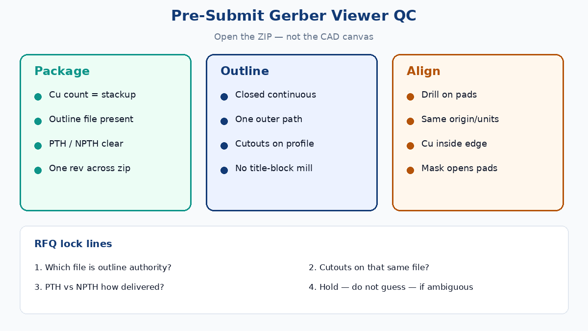
Pre-submit viewer QC checklist
Open the exported zip, not the CAD canvas. DRC green in the editor does not prove apertures, polarity, or outline export survived the job.
Package completeness
- Copper count matches stackup note
- Mask / silk present or intentionally omitted and noted
- Outline file present and named in README
- PTH and NPTH (or charted merged drill) present
- Same revision on every filename
Outline gate
- Exactly one outer closed path on the outline/mechanical file you declared
- Cutouts/slots visible where the drawing promises them
- Keep-out export (if included) contains constraints, not a second competing perimeter — or README says keep-out is unused by fab
- No title block on the mill file
Registration
- Drill overlays pad centers; no uniform shift
- Units/origin consistent Gerber ↔ drill
- Top/bottom not mirrored relative to each other unless intentional and noted
- Copper stays inside the finished outline with edge clearance you designed
Mask / silk sanity
- Pads that must solder are open in mask
- Silk off pads; pin-1 / polarity readable
- Gold-finger or test-point exposures match fab notes
Use a desktop viewer for NDA-sensitive jobs; online viewers are fine for non-sensitive prototypes if retention and access terms are acceptable. A viewer proves export fidelity. It does not replace fab DFM on annular ring, min trace/space vs copper weight, or impedance stack math — those stay on the quote capability sheet.
China fab RFQ questions that lock the outline gate
Put these in the RFQ or the first EQ reply so quotes stay comparable:
- Which filename is the authoritative board outline? (Attach README; if portal forces
.GKO, state the rename.) - Are internal cutouts and routed slots on that same outline file? List count/sizes if critical.
- PTH vs NPTH — separate files or hole chart? Any press-fit / tight-tol holes called on the fab drawing?
- Units and format — mm vs inch; coordinate format; zero suppression note if non-default.
- RS-274X only — confirm no RS-274D aperture wheel required; X2/X3 optional if both sides use it.
- Panelization — single-board outline in the zip; panel array drawing separate if you buy arrays.
- EQ rule — fab must hold (not guess) if multiple closed paths or missing outline appear in CAM.
Do not paste competitor portal checklists or claim plant-specific cycle times, prices, or “we always accept X.” Ask the quoted plant to confirm acceptance criteria in writing. XFPCB and any other shop should answer the same outline-authority questions; inventing capability numbers in the blog does not help CAM.
Release habit that survives the next spin
Treat Gerber release like a traveler stamp: regenerate all fab files after the last layout change, rebuild the zip, re-open in a viewer, re-read the README outline line, then upload. Partial re-exports (new copper, old outline) are how wrong-shape lots start. Keep keep-out for design rules. Keep mechanical/profile for the cut. Name the authority. That is the Gerber package outline gate.