
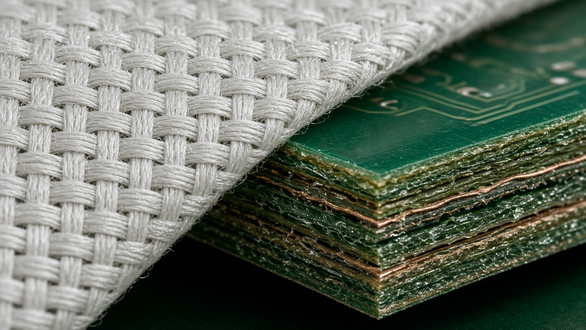
The glass fabric inside a laminate is the part of a PCB that most designers never specify and most buyers never see. Data sheets list a single dielectric constant, stack-up tables list a prepreg "style" number, and the conversation stops there. Yet the glass decides much of what the board does: how thick each dielectric layer presses out, how much resin sits between copper features, how uniform the dielectric looks to a fast differential pair, how cleanly a drill passes through, and how exposed the board is to conductive anodic filament growth between holes.
This article takes glass reinforcement as an engineering and procurement variable rather than a materials-science overview. It covers what weave styles differ in, why "spread" or "flat" glass exists, how fiber-weave effects show up as skew and impedance variation, what glass choice does to drilling and CAF, and how to write glass requirements into an RFQ without over-specifying. We write from XFPCB's fabrication floor, where glass style is a daily decision in lamination planning. For deeper coverage of the filament failure mode itself, see our article on conductive anodic filament prevention; for how prepreg sheets press out to thickness, see prepreg selection and pressed thickness.
What a glass style actually describes
Laminates and prepregs used in rigid PCBs are mostly reinforced with woven E-glass fabric, with lower-Dk and lower-loss glass types used in some high-speed materials. A glass "style" is a designation for a specific fabric: yarn type and filament diameter, the number of yarns per unit length in each direction (warp and fill), and the resulting fabric thickness and weight. Common style numbers you will see on a stack-up—such as 106, 1080, 2113, 2116, 1506, 7628—each describe a different construction.
Three characteristics matter most for the board:
- Fabric thickness and weight. Thicker, heavier fabrics carry less resin per unit thickness. Thin fabrics need more resin to fill the same thickness.
- Yarn count and openness. A fabric with fewer, thicker yarns leaves larger resin-rich windows between yarns. A fabric with more, finer yarns, or with yarns flattened and spread, is more uniform.
- Glass type. Standard E-glass is the default; low-Dk glass types are used where dielectric constant and loss must be lower and more uniform.
The same style can be used in different resin systems, and the same resin system is offered with several styles. When a stack-up says "2 × 1080" the style choice is already fixing a lot about thickness, resin content, and uniformity.
Resin content: the hidden variable
Glass and resin have very different dielectric constants: the glass is substantially higher than most epoxy and low-loss resins. The laminate's effective dielectric constant therefore depends on the glass-to-resin ratio. Laminate suppliers publish Dk and Df values per style and resin content for this reason—a "single" Dk for a material family is an average across constructions.
This has practical consequences:
- Two dielectric layers of the same nominal thickness can have different Dk if one is built from a thin, resin-rich style and the other from a heavier, glass-rich style.
- Pressed thickness depends on resin flow. Resin fills gaps between inner-layer copper features. A layer with heavy copper and large gaps loses more resin to fill, ending thinner. Fabric choice controls how much resin is available.
- Impedance models need the right Dk. Field-solver calculations using the "family" Dk rather than the construction-specific Dk can be off. Fabricators adjust trace width for the actual construction, which is one reason impedance-controlled stack-ups should be confirmed by the fab rather than fixed by the designer alone.
Open weave vs spread glass
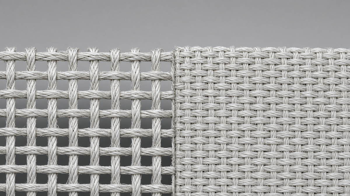
In a standard woven fabric, yarns cross over and under each other, leaving bundles of glass where yarns sit and resin-rich windows between them. At a scale of tens of micrometers—comparable to modern trace widths—the dielectric under a trace is not uniform. A trace that runs along a glass bundle sees a higher local Dk than one that runs over a resin window.
Spread glass (also called flat or mechanically spread glass) is produced by flattening and spreading the yarns so that they fill more of the fabric area, narrowing or closing the resin windows. The result is a more homogeneous dielectric, smoother surface, and often better laser drilling behavior for microvias, because the laser encounters a more uniform glass distribution.
Practical differences you can expect when moving from an open weave to spread glass:
- More uniform local Dk under traces, reducing fiber-weave-induced variation.
- More uniform resin distribution, which can help with thin dielectric control.
- Better consistency for laser-drilled microvias in HDI.
- Sometimes higher material cost and narrower availability in specific thicknesses and resin systems.
Spread glass reduces the fiber-weave effect; it does not eliminate it. For very high data rates, it is usually combined with layout and fabrication mitigations.
Fiber-weave effect: skew on differential pairs
The fiber-weave effect is the variation in propagation delay and impedance caused by a trace's position relative to the glass weave. For a single-ended trace, it shows up as impedance and delay variation from board to board and trace to trace. For a differential pair, it creates intra-pair skew when one leg runs predominantly over glass bundles and the other over resin windows. The two legs then propagate at different speeds, converting differential signal to common mode, increasing jitter and emissions, and closing the eye.
Several factors increase exposure:
- Long parallel runs aligned with the weave. Routing exactly parallel to the warp or fill direction keeps each leg on a consistent glass or resin path over a long distance.
- Open weave styles with large windows relative to the trace pitch.
- High data rates where small skew is a large fraction of the unit interval.
- Thin dielectrics where the trace sees more of the local glass structure.
Mitigation options
Mitigation combines material, layout, and fabrication choices. No single one is free.
- Spread or low-Dk glass for the layers carrying the most sensitive signals. This reduces the Dk contrast between bundle and window.
- Angled routing. Routing long runs at a small angle to the weave, or with periodic zig-zag, averages the glass exposure of both legs. This costs routing area and requires discipline in layout.
- Panel or artwork rotation. Rotating the board image on the fabrication panel by a small angle relative to the fabric's warp and fill directions averages the weave without changing layout. The cost is lower panel utilization, and it must be agreed with the fabricator, because it affects panel layout and sometimes registration planning.
- Pitch relationship. Choosing differential pair pitch relative to the glass bundle pitch so that both legs see similar glass coverage helps, but it depends on knowing the fabric style in advance and is sensitive to tolerances.
- Shorter parallel runs and careful length-matching do not fix weave skew, which is a velocity difference, but they reduce the distance over which it accumulates.
If you rely on panel rotation or a specific glass style for signal integrity, it must be written on the fabrication drawing; otherwise a later build may use a different, equally "compliant" construction. Our High Frequency PCB and Impedance Control PCB pages describe how we handle stack-ups where these choices matter.
Glass, drilling, and hole quality
Glass is abrasive and hard compared with resin and copper. Its style affects mechanical drilling and laser drilling:
- Drill wear and hole wall roughness. Heavier, glass-rich constructions wear drills faster and can leave rougher hole walls with glass protrusion. Rough walls make uniform plating harder and can trap chemistry.
- Wicking. Plating solution can travel along the interface between glass filaments and resin, producing copper "wicking" into the laminate from the hole wall. Excessive wicking reduces the effective spacing between holes and to adjacent copper.
- Laser drilling for microvias. Open weaves present the laser with alternating glass bundles and resin windows, producing variable via shapes. Spread glass and thin, uniform styles give more consistent microvia geometry.
These mechanisms are why fabricators often have preferred glass styles for particular hole sizes and aspect ratios, and why glass changes can show up as plating or reliability differences even when Dk and thickness are similar.
Glass and CAF exposure
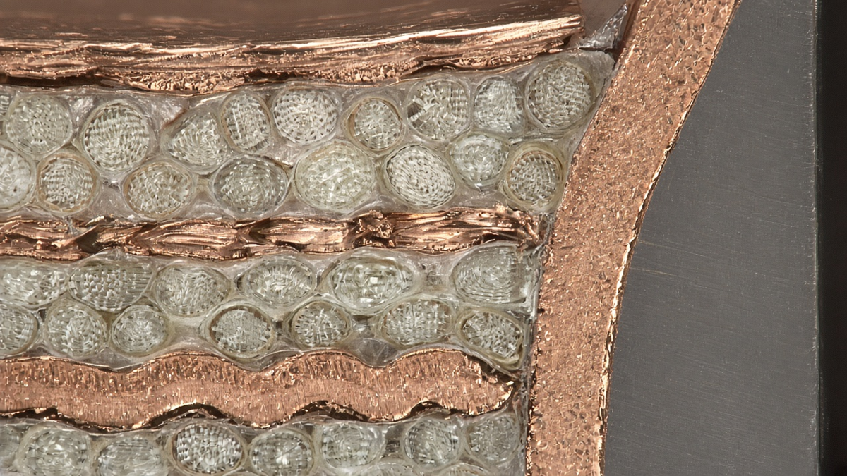
Conductive anodic filament growth occurs along the glass–resin interface between conductors at different potentials—typically hole to hole or hole to plane—under humidity and bias. The glass is the path. Factors include the quality of the glass–resin bond (coupling agent treatment), drilling damage that cracks the interface, wicking, the hole-to-hole spacing in the direction of the glass fibers, and the resin system's resistance.
Glass-related choices that reduce CAF exposure:
- Laminates qualified for CAF resistance by the supplier.
- Drilling parameters and drill maintenance that minimize interface damage.
- Hole-to-hole spacing that accounts for the fiber direction, especially for high-voltage nets.
- Avoiding glass styles or resin contents known to be problematic for a given hole density.
The CAF prevention article linked above covers the failure mode and test approach in more detail.
Dimensional stability and warpage
Glass provides the in-plane stiffness and low in-plane expansion of a laminate. Warp and fill directions of a woven fabric are not always identical in yarn count, and the laminate's in-plane properties can differ slightly by direction. This matters for:
- Registration. Layer-to-layer registration depends on the dimensional movement of cores through lamination. Fabricators characterize this by material and construction and scale artwork accordingly. A change of glass style changes the scaling.
- Warpage. Asymmetric use of glass styles across the stack-up—heavy glass on one side of the center, light on the other—contributes to bow and twist, alongside copper distribution. Symmetric constructions are easier to keep flat.
What to put on the RFQ and fab drawing
The right level of specification depends on how much the glass matters to your design.
For general digital boards without demanding signal integrity, specify the material family (by slash sheet of the relevant laminate specification, or by manufacturer and product), board thickness, and copper. Let the fabricator choose glass styles to meet thickness. Over-specifying styles here only reduces flexibility.
For impedance-controlled boards, give impedance targets and reference layers, and ask the fabricator to propose a stack-up with styles and resin content listed. Approve the stack-up, and require that styles not change without notice.
For high-speed boards with skew budgets, add:
- Which layers require spread glass or a specific low-Dk glass type.
- Whether panel or artwork rotation is required, and the acceptable angle.
- Whether particular styles are excluded for signal layers.
- That any change to glass style, resin system, or construction requires approval.
For high-voltage or high-reliability boards, specify CAF-resistant material, the relevant hole-to-hole spacing intent, and any qualification testing you require.
A useful drawing note looks like: "Stack-up per approved fabricator proposal revision X. Glass style, glass type, and resin content per that proposal. No construction substitution without written approval." That single sentence prevents most silent changes.
Common traps
- Assuming one Dk for the whole stack. Different styles in different layers have different Dk. Use the construction-specific values.
- Specifying glass styles that are not compatible with the target thickness or resin system, forcing the fabricator into EQs or unusual constructions.
- Requesting spread glass everywhere. It may be unnecessary on power and low-speed layers and can limit availability.
- Forgetting panel rotation costs. Rotated images use more laminate; agree it before quoting.
- Allowing silent substitution. Laminate shortages happen; without an approval requirement, a "compliant" alternative may change glass style and therefore skew and impedance.