
Buyers ask “what are aluminum PCBs used for” when a lighting module, power stage, or automotive lamp starts failing thermal lifetime on FR-4. The useful answer is not a museum list of old computer parts. It is a decision: when an aluminum metal-core PCB (MCPCB) is the right short thermal path, when FR-4 plus a heatsink still wins, and when a copper-base metal core is worth the premium. This guide stays applications-first for people who must pick a stack, fill a China fab RFQ, and keep junction temperatures inside the budget.
It does not replace a general aluminum thermal-design deep dive or a metal-core product capability page. Those already cover LED reflow quirks, TIM mounting notes, and shop menus. Here the focus is use cases, the Cu / dielectric / Al sandwich buyers must name, dielectric conductivity versus breakdown tradeoffs, and the RFQ fields that keep quotes comparable.
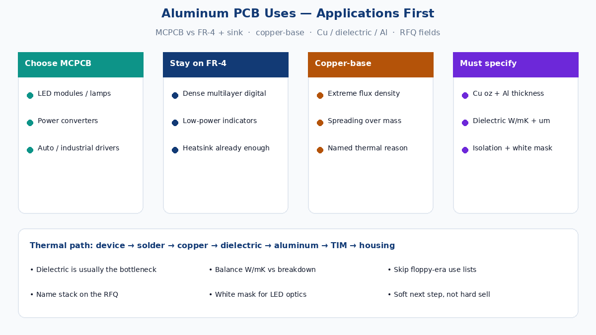
Where aluminum MCPCB actually earns its keep
Aluminum MCPCB exists to move heat out of a hot device into a stiff metal plate that can be bolted, clamped, or TIM-bonded to a housing. The circuit copper spreads heat laterally; the thin dielectric carries it vertically while holding voltage isolation; the aluminum base spreads and sinks. That path is short. FR-4 with pours and vias is longer and much more resistive thermally, even when a heatsink sits under the board.
LED modules and luminaires. High-brightness LED packages dump watts into a small footprint. Junction temperature drives lumen maintenance and color shift. Single-sided aluminum plates under COB arrays, linear light engines, and street-light modules remain the volume use case because the thermal path is honest and the outline is simple. White solder mask and optical cleanliness matter for lumen extraction — they are RFQ and process notes, not marketing fluff.
Automotive and vehicle lighting. Headlamps, DRLs, turn signals, and interior modules see vibration, under-hood or under-bumper heat, and long life expectations. Aluminum MCPCB gives mechanical stiffness and a mounting surface that mates to die-cast housings. Designers still must size dielectric isolation for the electrical architecture (12 V / 48 V / higher) and prove the TIM and fastener plan, not assume “metal board equals cool LED.”
Power converters and compact power stages. Synchronous bucks, LED drivers, electronic ballasts, and small inverters park MOSFETs, diodes, and magnetics on boards that run hot in sealed enclosures. When several watts of dissipation sit under a few square centimeters of copper, aluminum MCPCB often beats hoping FR-4 copper planes will carry heat to a distant sink. Audio amplifiers that run Class-D power stages in small chassis fall in the same bucket — heat, not nostalgia, drives the stack choice.
Industrial drivers and motor control plates. Stepper and BLDC driver modules, industrial LED drivers, and dense DC-DC bricks on DIN-rail or machine panels benefit when the aluminum plate is the primary heat spreader into a chassis wall. Isolation ratings, creepage on the copper layer, and dielectric thickness become electrical-safety items as much as thermal ones.
Exclude floppy-era computer folklore. Modern compute rarely needs aluminum MCPCB for the logic board; power bricks, GPU coolers, and server VRMs that do need metal cores are discrete thermal subsystems, not “the motherboard is aluminum.”
When FR-4 plus heatsink still wins
Aluminum is not automatic for every warm board.
Dense multilayer digital. MCU, FPGA, and high-speed digital need buried signal / power / ground planes, fine vias, and often controlled impedance. Single-sided MCPCB cannot host that stack. Hybrid approaches (FR-4 control board + aluminum LED or power plate) exist, but they add connectors, harness, and assembly cost. If the heat load is modest and a heatsink or chassis contact under FR-4 already meets Tj, stay on FR-4.
Routing density and double-sided parts. Through-hole connectors on both sides, dense BGA escape, and buried vias fight classic single-sided aluminum construction. Double-sided aluminum and multilayer metal-core builds exist; they cost more, complicate vias, and need early manufacturing engineering. Do not force aluminum because a competitor brochure lists “computer components.”
Cost-sensitive low-power LED. Indicator LEDs and low-lumen strips often survive on FR-4 with copper pours. Paying for thermal dielectric and aluminum base only makes sense when lifetime, lumen, or enclosure limits force it.
Isolation-first, heat-second designs. Some safety-isolated stages want thick dielectric or slot isolation that fights thin high-conductivity thermal dielectrics. Here FR-4 (or a thicker dielectric metal-core grade) may be the honest electrical choice even if thermal resistance rises — then you compensate with copper area, airflow, or a separate heatsink.
When copper-base (or other metal cores) beats aluminum
Aluminum wins most lighting and ballast-class jobs on weight, cost, and thermal spreading. Copper-base metal cores appear when lateral conductivity and heat spreading under extreme flux density matter more than mass and material price — compact high-current converters, some laser diode plates, and niche RF power front-ends. Steel-base shows up where mechanical strength or CTE matching dominates. Treat copper-base as a deliberate upgrade with a named thermal and mechanical reason, not as a default “premium aluminum.”
Buyers should ask the fab which base alloys and dielectric systems they already process. A shop that runs aluminum lighting plates daily may treat copper-base as a special; quoting both without process fit wastes weeks.
The stack buyers must specify: Cu / dielectric / Al
A typical single-sided aluminum MCPCB is three functional layers. Calling it “FR-4 with metal on the back” confuses CAM and under-specifies the RFQ.
Circuit copper. Foil weight (commonly 1 oz / 2 oz, sometimes heavier) sets lateral spreading and current capacity. Thicker copper helps current and spreading; it also changes etch geometry and thermal mass for reflow. Name finished copper weight, not only starting foil.
Thermal dielectric. Electrically insulating, thermally conductive layer between copper and aluminum. Thickness often lands in a roughly 75–150 µm window for lighting-class builds, but voltage and thermal targets decide. Conductivity is commonly discussed in the ~1–3 W/m·K class for volume grades, with higher-conductivity systems available at higher cost and sometimes different process windows. This layer is usually the thermal bottleneck — aluminum itself spreads well once heat arrives.
Aluminum base. Alloy and thickness (for example 1.0 mm / 1.5 mm / 2.0 mm class plates) set spreading, stiffness, and machining for mounting holes. Surface finish on the metal side (bare, anodized, or other) affects TIM wetting and corrosion in the field. Outline, V-cut or routing, and hole-to-edge rules belong on the mechanical drawing.
Heat flows roughly: device → solder → copper → dielectric → aluminum → TIM → housing or sink. Every interface has resistance. Specifying only “aluminum PCB” without dielectric W/m·K, thickness, copper weight, and base thickness is how two fabs return two different thermal realities at two different prices.
Dielectric: thermal conductivity vs breakdown
Marketing sheets love a single W/m·K number. Production and safety care about the pair: thermal resistance and dielectric withstand.
Higher conductivity lowers the temperature rise through the dielectric for a given thickness. Thinner dielectric also lowers thermal resistance — and shrinks the voltage isolation margin. Thicker or lower-conductivity dielectric protects isolation and often peel strength, at the cost of hotter junctions.
Design from voltage class, working temperature, and required thermal resistance together. A 48 V automotive string and a mains-referenced driver do not share the same isolation story as a low-voltage LED strip. Ask the fab for the dielectric system’s rated breakdown or withstand guidance at the thickness you intend to buy, and keep creepage on the copper layer honest with slots or mask where the safety file demands it.
Peel strength, Tg or thermal endurance of the dielectric, and reflow / wave limits matter for assembly yield. LED aluminum boards often see different thermal mass and peak profiles than FR-4 of the same outline — call reflow expectations in the assembly package when you buy fab + PCBA together.
Application checklist before you lock the stack
Walk the product, not the brochure:
- Where do the watts go? Package power, duty cycle, ambient, and allowed Tj or Tc.
- What is the sink? Extrusion, die-cast housing, cold plate, or free air? TIM type and clamp force.
- What voltage and isolation? Working voltage, surge, and safety standard drive dielectric thickness more than a W/m·K headline.
- What routing lives on the metal core? LED only, power FETs only, or mixed signal that really wants FR-4?
- What optical and mask needs? White mask reflectivity for LED, dam openings, and cleanliness for lenses.
- What mechanical features? Countersinks, press-fit studs, selective machining, and edge rails change fab process.
If steps 1–2 already close with FR-4 and a sink, aluminum is optional. If steps 1–3 force a short path into metal, aluminum MCPCB is on the table. If flux density or spreading still fails aluminum, evaluate copper-base with the fab.
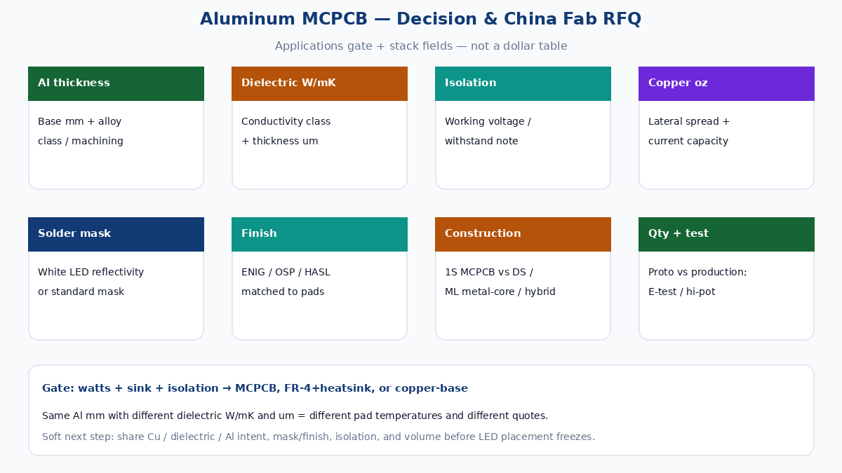
China fab RFQ fields that keep aluminum quotes honest
Weak RFQs say “aluminum LED PCB, 1.6 mm, white mask” and leave dielectric and isolation to imagination. Strong RFQs name the thermal sandwich and the acceptance rules.
| Field | Why the shop needs it |
|---|---|
| Base metal and thickness | Aluminum alloy class and mm thickness (or copper-base if intentional) |
| Dielectric thermal conductivity | Target W/m·K class or named dielectric system the fab stocks |
| Dielectric thickness / isolation | µm or mil thickness plus withstand or working-voltage note |
| Copper weight | oz or µm, start vs finished if you care |
| Layer construction | Single-sided MCPCB vs double-sided / multilayer metal-core / hybrid |
| Solder mask | Color (often white for LED), finish, dams, and keep-outs |
| LED / optical notes | Reflectivity expectation, cleanliness, no-silkscreen zones under lenses |
| Surface finish | ENIG, OSP, HASL lead-free, etc., matched to LED pad and shelf life |
| Outline and machining | Exact contour, V-cut vs route, mounting holes, countersink, tolerance |
| Quantity and revision | Proto vs production band; freeze Gerber / drawing revision |
| Test and acceptance | E-test, dielectric withstand sample if required, visual class |
| Assembly (if turnkey) | LED MPN / binning, TIM responsibility, reflow limits, AOI / test |
Dielectric guidance is the gap most thin application lists skip. Two boards with the same aluminum thickness and copper weight can differ by tens of degrees at the LED pad if one uses a thin high-conductivity dielectric and the other a thick commodity grade. Put W/m·K and thickness (or a named system plus isolation) on the same line as aluminum thickness.
White mask for LED is not only cosmetics. Reflectivity and yellowing under heat and light affect delivered lumens. If optical performance matters, say so; if the board is a hidden driver plate, standard mask may be enough and cheaper.
Do not invent dollar tables or certificate claims on the RFQ cover sheet. Ask for process capability that matches your drawing. Soft next step: send outline, stack intent (Cu / dielectric W/m·K / Al thickness), copper weight, mask/finish, isolation note, and volume band before LED placement freezes pad size and TIM area.
Soft next step
Aluminum PCB uses cluster where heat, stiffness, and a short path into metal matter — LED modules, automotive lamps, power converters, and industrial drivers. FR-4 plus heatsink still wins for dense digital and low-power work. Copper-base is a targeted upgrade when spreading and flux density outgrow aluminum’s commercial balance. Lock the Cu / dielectric / Al stack, balance dielectric conductivity against breakdown, and fill China fab RFQ fields tightly enough that quotes describe the same thermal path. Share that package with manufacturing engineering early; the right metal-core choice is a thermal and isolation contract, not a materials buzzword.