
Industrial buyers do not fear “what is switchgear” as a definition. They fear a control board that trips late, talks dirty on RS485 after a surge, or scrapes isolation because creepage and slots never made the China fab RFQ. Electrical switchgear is the assembly that controls, protects, and isolates power — and the control PCBA is the low-voltage brain that senses, decides, drives coils, and reports status. This factory note covers types, switchboard vs switchgear for PCB scope, how control boards fit the power path, RFQ callouts CAM actually checks, mixed SMT+THT realities, and a functional test matrix shops should run before ship.
What electrical switchgear is
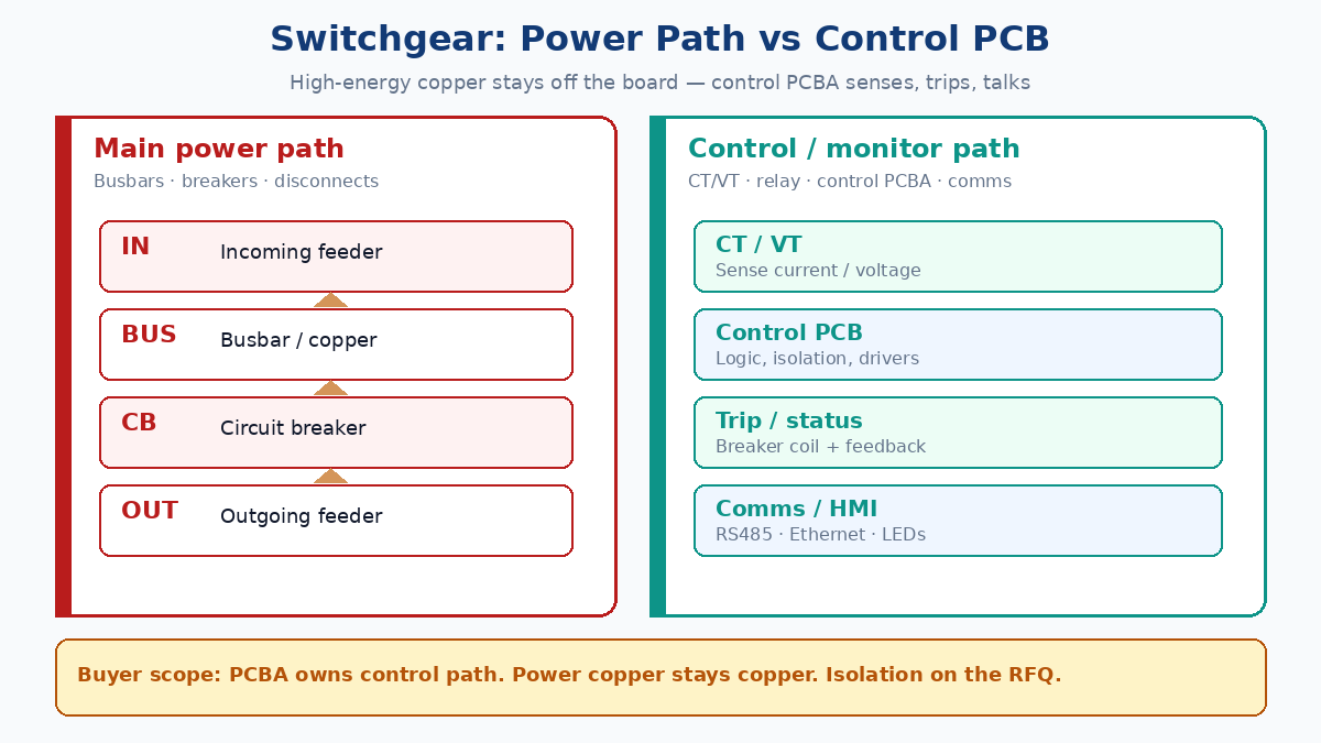
Electrical switchgear is a centralized set of switching, protecting, and isolating devices that manage power flow, isolate equipment for maintenance, and interrupt faults (overloads, short circuits, ground faults). Typical hardware includes circuit breakers, disconnect switches, fuses, protective relays, CT/VT sensors, busbars, meters, and control panels.
It shows up in factories, utilities, commercial buildings, data centers, and renewables. Voltage class is the usual first cut: low-voltage (LV, commonly under 1 kV), medium-voltage (MV), and high-voltage (HV). Insulation medium is a second cut — air-insulated, gas-insulated, or vacuum — but the control electronics problem is the same: keep power energy on copper and busbars; keep sensing, logic, and communication on a repeatable PCBA.
How switchgear works (power path vs control path)
Under normal load, power enters, crosses busbars and switching devices, and feeds outgoing circuits. CT/VT and other sensors watch current, voltage, and often temperature or status contacts.
When a fault signature appears, the protection path — relay logic or a control PCB — issues a trip. The breaker opens, the faulted section isolates, and alarms or remote signals fire.
Simplified flow:
Power in → CT/VT / sensor monitor → protective relay or control PCB → breaker trip → isolate → alarm / remote
Two paths matter for PCB buyers:
| Path | What it carries | PCB role |
|---|---|---|
| Main power | Feeder current, fault energy, busbar copper | Usually not on the control board |
| Control / monitor | Sense signals, logic, coil drive, status, comms | Control PCBA, relay board, HMI, PSU, interface |
Do not quote a control board as if it “handles the main power.” It senses and commands. Mis-scoping that on a PO is how teams order the wrong stackup and wrong isolation.
Components and PCB roles
| Switchgear part | Main job | Related PCB / PCBA role |
|---|---|---|
| Circuit breaker | Interrupt fault current | Trip command, coil drive, status feedback |
| Disconnect switch | Isolate for maintenance | Position sense, interlock |
| Fuse | Overcurrent protection | Coordination / input protection on control side |
| Protective relay | Detect abnormal conditions | MCU logic, sensing AFE, isolation, drivers |
| CT / VT / sensors | Measure parameters | Analog front-end, isolation, conditioning |
| Control panel / HMI | Local operate & indicate | Button, LED, display boards |
| Communication module | Remote data / SCADA | RS485, CAN, Ethernet, wireless — with surge/ESD |
| Control power supply | Feed electronics | AC-DC or DC-DC board |
| Surge protection | Clamp transients | TVS, MOV, fuse, common-mode choke placement |
A protective-relay style board typically mixes isolated sense inputs, MCU logic, opto or magnetic isolation, relay drivers with coil kickback protection, and feedback. A comms board that skips surge parts at the connector is a field-failure pattern, not a “feature.”
Types: LV / MV / HV and insulation
Low-voltage (LV, commonly <1 kV): Buildings, light industrial, data-center distribution. Control boards often cover metering, breaker control, status, and industrial comms. Isolation still matters at interfaces and PSU sections — “LV” does not mean “no creepage notes.”
Medium-voltage (MV): Plants, utilities, larger feeders. Stronger insulation and isolation expectations on both primary gear and secondary control. Control PCBA should treat creepage/clearance, surge, EMI, and long-life soldering as first-class RFQ items.
High-voltage (HV): Transmission / substation class. Primary gear is specialized; control and IED-style electronics still need industrial-grade assembly and test. Exact primary voltages and standards belong on the equipment spec — do not invent clause numbers on a PCB quote.
By insulation medium: Air-insulated, gas-insulated, vacuum. Medium choice drives enclosure and primary design more than copper thickness on the control board — but humidity, pollution degree, and enclosure sealing drive whether you ask for conformal coat or potting on the PCBA.
Switchboard vs switchgear — PCB scope decision
Buyers search “switchboard vs switchgear” because the words get mixed in RFQs. For procurement of PCB work, use this cut:
| Item | Switchgear | Switchboard |
|---|---|---|
| Main role | Control, protect, isolate, interrupt faults | Distribute power to multiple circuits |
| Protection depth | Higher fault isolation / interruption intent | Distribution-focused |
| Typical devices | Breakers, relays, fuses, disconnects, sensors | Breakers, meters, panel controls |
| Voltage range | LV / MV / HV | Mostly LV distribution |
| PCB scope | Control, relay, sensing, isolation, industrial comms, functional trip test | Metering, display, simpler control; lighter trip matrix |
Procurement rule of thumb: If the board must inject CT/VT-like signals, drive trip coils, survive surge on field wiring, and prove isolation zones, treat the project as switchgear control PCBA. If it is mostly metering LEDs and a clean LV panel, a lighter switchboard-style RFQ may be enough — still call finish, class, and test, but do not over-buy MV isolation theater without evidence.
Smart grid trends (what changes on the board)
Traditional gear was local and mostly mechanical. Intelligent switchgear adds sensors, digital meters, microprocessor relays, and remote monitoring. That does not remove breakers; it adds PCBA demand:
| Function | Electronics | PCBA pressure |
|---|---|---|
| Remote monitoring | Comms module | Surge / EMC at connector |
| Fault detection | Sense + relay logic | Isolation + AFE accuracy |
| Predictive maintenance | Data acquisition | Stable analog, burn-in |
| Local HMI | Display / LED / keys | Mixed tech, clear silk |
| Breaker control | Driver board | Coil protection, soak test |
| Grid / plant link | Industrial interface | ESD, common-mode, grounding notes |
Why the control PCB matters
If the control PCBA fails, the copper gear may still sit in the cubicle — but monitoring, remote trip, alarm, or SCADA link can be blind. Common sections on one board (or a small set):
- Power input and conversion
- Relay / breaker drive
- Voltage and current sensing (secondary side)
- Protection / fault logic
- Communication
- Indicators / HMI
- Status feedback and interlocks
These boards mix analog, digital, power, and industrial I/O. That is why shops that only stencil SMT and skip THT fixtures struggle on relay + terminal-block builds.
PCB design that survives the cubicle
Creepage, clearance, isolation slots (RFQ language)
When the board has isolated sense, PSU primary, or field-wired interfaces, mark:
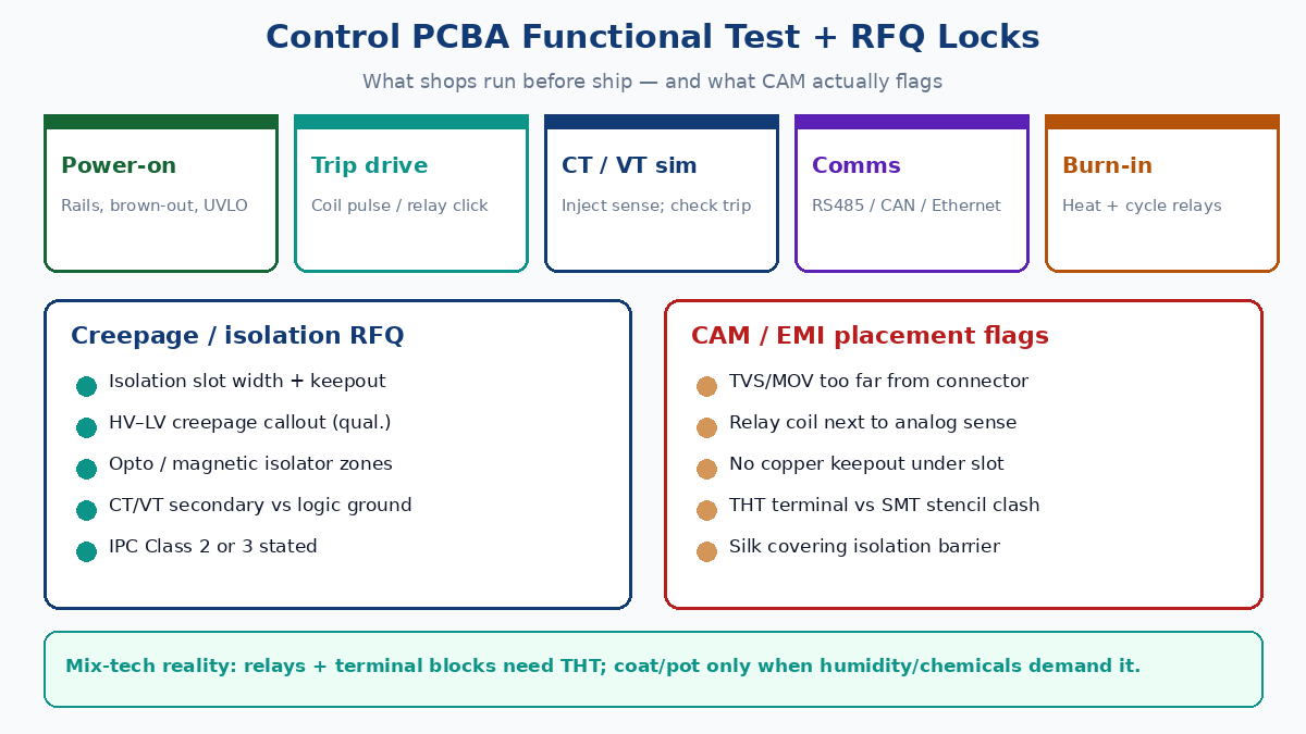
- Isolation barrier / slot — width, keepout, no copper under the slot, no silk across the barrier.
- Creepage / clearance intent — state zones (e.g. CT secondary vs logic, mains-side PSU vs SELV). Exact mm values belong to your insulation diagram and pollution degree — if unknown, mark “per equipment insulation drawing; do not reduce CAM-flagged clearances.”
- Isolator placement — optocouplers, digital isolators, transformers: keep primary/secondary pads on correct sides of the barrier.
- Grounding intent — chassis vs logic vs shield; do not leave “single ground” as a verbal hope.
Phrases that stick on China fab notes:
- “Isolation slot as drawn; no copper, vias, or silk across barrier.”
- “HV–LV / primary–secondary clearances per drawing; do not shrink for panel yield.”
- “IPC Class 2 (or Class 3) — state one.”
Phrases that do not stick:
- “High voltage safe” with no zone map
- “Follow IEC” with no drawing and no qualitative zones
- “Any equivalent isolator OK”
Surge, ESD, EMI — placement CAM flags
External connectors see field wiring. Put TVS/MOV/fuse/common-mode parts at the connector, not three inches inland. Separate relay coil loops from analog sense. Keep clock / MCU away from noisy coil return. CAM and DFM reviews commonly flag:
- Surge parts too far from the entry connector
- Relay next to high-impedance analog
- Copper fill under an isolation slot
- THT terminal footprints colliding with SMT paste rules
- Silk text bridging isolation
Thermal and mechanical
Relays, regulators, and terminal blocks need copper pour or spacing, strong THT fillets, and clear polarity marks. Test points for trip and sense nets save hours of bed-of-nails debate later.
Mixed-tech assembly realities (factory)
Most switchgear control boards are not pure SMT:
| Element | Why it is there | Shop reality |
|---|---|---|
| Power relays / contactors (board-level) | Coil drive, dry contacts | Often THT; need selective or wave / hand after SMT |
| Terminal blocks | Field wiring | THT or press-fit; height vs reflow profile |
| Large electrolytics / transformers | PSU bulk | Mixed process; orientation marks matter |
| Fine-pitch MCU / isolators | Logic | SMT first; then THT |
| Conformal coat | Humidity / pollution | After clean and optional ICT; mask connectors / test pads |
| Potting | Severe vibration / chemical splash | Rare on all boards; use when enclosure does not protect |
When to coat: damp / polluted environments, coastal, outdoor cabinets without sealed electronics volume. When to pot: severe shock/vibe or chemical exposure that coat cannot handle — and accept rework pain. Do not coat “because quality” if connectors and test pads were never masked; that creates scrap and false opens.
Call SMT + THT, fixture needs, and coat/pot explicitly on the RFQ. Vague “full turnkey” without process order is how relays arrive tombstoned or terminals float.
Inspection and functional test matrix
AOI catches missing parts, polarity, bridges. For switchgear control PCBA, functional test is the buyer’s real insurance:
| Test | What you prove | Notes |
|---|---|---|
| Power-on | Rails in range, UVLO / brown-out behavior | Log limits; reject silent “LED on” |
| Trip drive | Coil pulse / relay actuation / contact feedback | Include kickback path check |
| CT / VT simulation | Inject secondary-level sense; verify trip / threshold | Do not require live MV primary on the bench |
| Comms | RS485 / CAN / Ethernet link + basic packet / loopback | Surge path visually checked at connector |
| I/O & indicators | Status LEDs, dry contacts, interlocks | Match HMI map |
| Burn-in / aging | Soak under load / heat; cycle relays | Use when field ambient is harsh or Class 3 intent |
Bare-board E-test still matters. ICT helps on dense SMT. Neither replaces a trip-and-sense functional script tied to the protection scheme.
⚠️ Watch out: A board that “passes AOI” can still fail when the trip FET never fires under simulated CT current, or when RS485 dies after the first ESD hit because the TVS sat on the wrong side of the connector. Write the matrix into the PO.
RFQ checklist (China PCBA)
- Gerber + drill, BOM with MPNs, CPL for SMT, fab notes with stackup/finish.
- Isolation slot / creepage zones called; IPC Class 2 or 3 stated.
- Mixed-tech process order: SMT → THT → clean → (ICT) → functional → (coat).
- Relay and terminal MPNs locked; no silent coil substitutes.
- Surge/ESD parts at connectors; CAM keepouts honored.
- Functional matrix: power-on, trip drive, CT/VT sim, comms, optional burn-in.
- Coat/pot only if environment demands it; mask list attached.
- AVL / no-sub for isolators, MCUs, and protection parts.
Closing
Electrical switchgear controls, protects, and isolates power. Switchboards mostly distribute. Control PCBs live on the low-voltage intelligence path — and field failures cluster where isolation, surge placement, mixed-tech assembly, and trip functional test were never written into the RFQ. Put creepage/slots, SMT+THT order, and the test matrix on the traveler, and the cubicle stays boring — which is the goal.
Related reading (titles only): IPC Class 3 PCB fabrication; How PCB assembly works; SMT vs DIP PCB assembly; Through-hole PCB assembly process; PCB DFM design for manufacturing.