
A flex-cut keyboard PCB is still a rigid FR-4 board with routed slots that lower local stiffness so the typing zone can move a little under keypress. A non-flex-cut board keeps a more continuous laminate for firmer support and simpler fab/assembly. Builders compare the two for feel; overseas buyers and sourcing engineers need the manufacturability side: slot DFM, hotswap socket support near cuts, panel rails, assembly fixtures, and a China fab RFQ checklist. This page is that tradeoff — keyboard feel + fab/PCBA reality. It is not a polyimide flexible or rigid-flex design guide; those use different materials and process stacks.
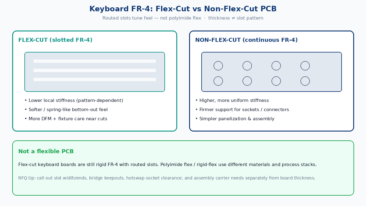
Quick answer: pick by feel goal and fab risk
- Name the technology — flex-cut = slotted FR-4 keyboard PCB; not polyimide flex, not rigid-flex, not semi-flex depth-mill.
- Separate thickness from cut map — 1.2 mm vs 1.6 mm and slot pattern are independent levers; do not mix them in one “more flexible” claim.
- Match pattern to risk — long/zoned cuts usually leave more routing room; dense per-key cuts raise bridge, routing, and socket-support risk.
- Protect hotswap sockets — keep slots away from socket pads/anchors; plan support during switch insertion and SMT.
- RFQ the geometry — min slot width (router), rounded ends, min FR-4 bridge width, copper-to-slot clearance, tab locations.
- Budget fixtures — thin or heavily slotted panels often need stronger rails, careful breakaways, and an assembly carrier.
💡 Factory gain: Put the cut map, finished thickness, copper weight, hotswap keepouts, and “assembly carrier required Y/N” on the fab drawing and RFQ. Vague “flex PCB” wording gets quotes for polyimide flex — wrong process, wrong price, wrong stack.
Flex-cut vs non-flex-cut at a glance
| Factor | Flex-cut keyboard PCB | Non-flex-cut keyboard PCB |
|---|---|---|
| Structure | FR-4 with intentional routed slots / bridges | More continuous FR-4 outline |
| Local stiffness | Lower; pattern-dependent | Higher; more uniform |
| Typing feel goal | Softer / more spring-like local movement | Firmer, more direct bottom-out |
| Routing area | Interrupted by slots | More continuous channels and planes |
| Socket / connector support | Weaker near heavy cuts | Stronger mechanical backing |
| Design & CAM complexity | Higher | Lower |
| Panelization / assembly | May need rails, carriers, careful tabs | Usually simpler |
| Relative cost drivers | Extra routing time, fixtures, yield risk | Usually lower for similar stack/finish |
Neither is “better” in absolute terms. Flex-cut buys mechanical tuning; non-flex-cut buys structural margin and process simplicity.
Critical distinction: slotted FR-4 ≠ flexible PCB
| Type | Typical material | Where “flex” comes from | Typical use |
|---|---|---|---|
| Flex-cut keyboard PCB | FR-4 (rigid) | Routed slots and narrow bridges | Mechanical keyboards |
| Flexible PCB | Polyimide (or similar) | Flexible dielectric | Wearables, cameras, dynamic flex assemblies |
| Rigid-flex | FR-4 + polyimide | Integrated rigid and flex regions | Compact 3D interconnect |
| Semi-flex | Locally thinned rigid laminate | Controlled-depth milling | Bend-to-install (not keyboard feel slots) |
If your RFQ says “flex PCB” without a cut map and FR-4 callout, many China fabs will price polyimide flex or ask clarifying questions that burn a week. Say “FR-4 keyboard PCB with routed flex-cuts” and attach Gerbers + a mechanical sketch of the slot pattern.
What a flex-cut actually changes
Slots remove laminate so remaining FR-4 bridges carry bending load. That changes:
- Local stiffness under finger force
- Load sharing between neighboring keys
- Vibration paths through the board
- Available copper routing and plane continuity
- How much FR-4 remains under hotswap sockets and connectors
Two boards can share the same laminate brand and thickness yet feel different because slot length, density, bridge width, and mounting points differ. Plate material, case mount (gasket, top, tray), foam, switches, and keycaps still dominate sound and final feel — the PCB is one spring in a stack, not the whole instrument.
Flex cuts do not change switch actuation force, firmware debounce, scan rate, or USB latency. Do not sell them as an electrical upgrade.
Thickness and slot geometry are separate levers
Under similar support, a thinner board usually deflects more than a thicker one. A 1.6 mm continuous board is generally stiffer than a 1.2 mm continuous board. Cutting slots on either thickness further reduces local stiffness.
Compare apples to apples:
- Same thickness, flex-cut vs non-flex-cut → isolates the cut pattern
- Same cut map, 1.2 mm vs 1.6 mm → isolates thickness
Mixing a thin flex-cut against a thick solid board confuses both variables. Also check mechanical parts: many PCB-mount stabilizers and switch footprints are designed around common 1.6 mm thickness; thinner boards can feel loose or need different hardware — confirm with your mechanical BOM, not a blog default.
Common flex-cut patterns (and fab risk)
Long cuts — long horizontal or vertical slots softens a wide region and often leave better routing corridors than dense per-key maps. Watch stress at slot ends, panel stiffness, and plane splits.
Zoned cuts — slots around Spacebar, Enter, or the home-row zone tune local feel while leaving stronger islands elsewhere. CAM must keep zone boundaries clear of critical nets and sockets.
Per-key cuts — partial isolation around each switch for localized movement. Highest design risk: narrow bridges, cramped routing, weak socket support, longer profiling time, and more sensitivity to handling.
Hybrid maps — mix of the above for region-specific stiffness. Requires close coordination between mechanical layout, copper, component placement, and assembly support.
Typing feel and sound — what to promise
Flex-cut boards often allow more local movement (softer or more spring-like bottom-out). Solid boards usually feel firmer and more direct. Final sound still depends on plate, case cavity, foam, switches, keycaps, stabilizers, and mount method. Treat “deeper flex = quieter” as marketing folklore until you validate the full build.
DFM: slots, copper, and keepouts
Slot geometry
Match minimum slot width to the fab’s router capability. Narrow slots need smaller tools, more machine time, and tighter dimensional control. Prefer rounded slot ends and smooth transitions to reduce stress concentration at corners.
State on the drawing:
- Min slot width and preferred tool diameter class
- Min remaining FR-4 bridge width between slots
- Any “no-tab / no-clamp” zones on narrow bridges
Copper and routing clearance
Keep copper, vias, pads, and soldermask openings adequately clear of slot walls. Exact spacing depends on thickness, copper weight, layer count, routing tolerance, and factory capability — put your agreed clearance on the fab notes rather than inventing a universal micron claim.
Avoid packing critical high-density vias at slot ends. Narrow bridges should not carry crowded multi-net bundles if you can route elsewhere.
Ground and return paths
Slots can slice planes and interrupt return current. Review USB differential pairs, ESD paths, wireless module grounds, charging circuits, and LED power distribution so return paths remain intentional after the cut map is frozen.
Hotswap sockets and heavy parts
Each hotswap socket needs enough surrounding FR-4 to survive repeated switch insertion and removal. Do not run slots through or hard against socket pads/anchors. Place USB connectors, batteries, and large connectors on well-supported islands — not on skinny flex bridges. Plan mechanical support when end users hotswap switches on a slotted board.
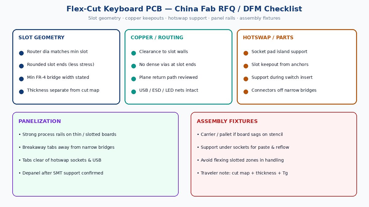
Manufacturing, panelization, and assembly fixtures
During CAM, the fab should review slot geometry, router diameter, bridge width, copper-to-slot clearance, and component-to-slot spacing. Thin or heavily slotted keyboard panels often need:
- Stronger process rails so the panel does not flap during etch, plating, or scoring
- Breakaway tabs placed away from narrow bridges, hotswap fields, and connectors
- An assembly carrier or pallet so the board does not sag under stencil print, pick-and-place, or reflow
- Controlled depaneling that does not twist slotted zones
Profiling of FR-4 flex-cuts is still a rigid PCB routing/scoring problem — not a flex coverlay process. Method and tolerance belong in the quote conversation with your thickness and slot map attached.
Reliability checks worth writing into NPI
- Electrical: matrix continuity, interface (USB/wireless), LED rails
- Mechanical: deflection under representative load, recovery, permanent set
- Hotswap: repeated insert/remove cycles on sockets nearest cuts
- Handling: drop/twist of slotted panels during pack and DIY assembly
Failures to watch: cracked copper at slot ends, lifted pads on under-supported sockets, intermittent opens after flex cycles, and panel scrap from tab tear-out into a bridge.
China fab RFQ checklist (keyboard flex-cut)
Send with every RFQ / ECO:
- Gerbers + drill + fabrication drawing calling out FR-4, finished thickness, copper weight, surface finish, soldermask/legend.
- Explicit note: routed flex-cuts on rigid FR-4 — not polyimide flex / not rigid-flex.
- Cut map or mechanical layer with min slot width, rounded ends, min bridge width.
- Copper-to-slot and pad-to-slot keepout rules (or ask fab to propose and approve).
- Hotswap socket footprint + keepout from slots; mark “support required for switch insert.”
- Panelization preference: rail width, tab style/locations, “no tabs on bridges.”
- Assembly notes: carrier/pallet Y/N, max warpage expectation for SMT, double-sided process if any.
- Quantity, lead time, E-test requirement, and whether first articles include mechanical deflection photos.
When to choose which
Prefer flex-cut when the product story needs tunable local movement, the cut map is DFM-reviewed, sockets sit on solid islands, and you accept fixture/routing cost.
Prefer non-flex-cut when you need maximum socket and connector support, simpler quotes, denser routing or unbroken planes, aggressive cost/lead-time, or the feel goal is already met by plate/mount/foam without cutting the PCB.
Many commercial builds ship solid FR-4 successfully. Flex-cut is a deliberate mechanical feature — treat it like any other specialty fab option: specify it, fixture it, and validate it.
Bottom line for buyers
Flex-cut vs non-flex-cut on a keyboard PCB is a stiffness and support tradeoff on rigid FR-4, not a materials swap to polyimide. Get feel goals from the mechanical team, then translate them into slot geometry, keepouts, panel rails, and assembly fixtures the fab can quote. Clear FR-4 + flex-cut language on the RFQ prevents wrong-process quotes and protects hotswap reliability next to the cuts.