
A PCB short circuit — unintended connection between nets, especially VCC–GND — is one of the fastest ways a board overheats, trips a lab supply, or fails first power-up. Overseas techs and engineers usually land here after a continuity beep on the power rail, a burned regulator, or a lot that passed AOI yet draws excess current. This page is that narrow factory/lab workflow: confirm safely, separate fab vs assembly origins, isolate the section, use current-limited thermal clues, rework the bridge or part, and decide when to scrap. Not a general repair or open-trace guide — here the job is short diagnosis and fix.
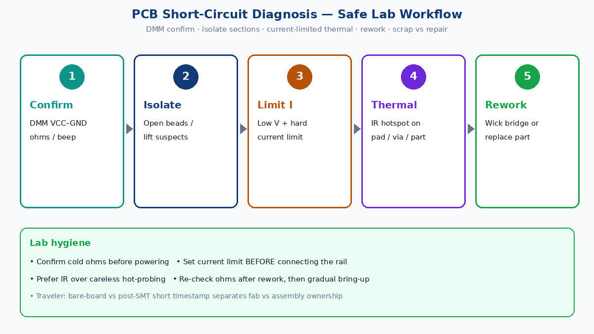
Quick answer: safe short-find workflow
- Confirm, don’t guess — DMM continuity/resistance between the suspect nets (often VCC–GND). Near-zero ohms or a solid beep is a short; tens of ohms may be a loaded rail or a leaky part — note the number.
- Power only with a current-limited supply — if you must energize, start low voltage with a tight current limit. Do not hot-probe carelessly on an unlimited bench supply.
- Isolate sections — remove fuses/jumpers, lift ferrite beads, desolder one rail branch or suspect part at a time so the ohm reading climbs when the shorted island leaves the net.
- Locate with heat clues — under limited current, a thermal camera (or brief, careful touch with PPE judgment) finds the hottest pad, pin, or via cluster.
- Fix the cause, then re-verify — wick bridges, replace shorted caps/ICs, clear debris; re-check ohms before full functional voltage.
- Scrap vs repair — surface solder bridges and discrete shorts are usually worth fixing; buried inner-layer plane shorts on cheap boards often cost more than a remake.
💡 Factory gain: Write the rail name, measured ohms (before/after isolation), and whether the short existed on bare board vs after SMT on the traveler. That single timestamp separates etch/drill/lamination faults from paste bridges and shorted parts — and stops endless rework on the wrong process owner.
What a short looks like on the bench
| Symptom | What it usually means | First check |
|---|---|---|
| VCC–GND continuity ~0 Ω cold | Hard short on power plane or part | Confirm on bare vs assembled board |
| Supply current-limits immediately | Hard rail short still present | Do not raise current “to see smoke” |
| Board warm in one zone under limited bias | Localized short or shorted component | Thermal map that zone |
| Intermittent beep when flexed | Debris, cracked via, whisker, or cold bridge | Microscope + flex test under DMM |
| Only one panel position fails | Paste/placement or local fab defect | Compare siblings; check stencil/AOI |
A short is a low-resistance path that should not exist. Power-rail shorts matter most because planes have huge copper area and little series resistance — current spikes hard. Signal-to-signal bridges can still brick an IC; treat them with the same confirm → isolate → fix discipline.
Fab vs assembly: where the short started
Knowing when the short appeared saves days of argument between fab and SMT.
Likely fab / bare-board origins
- Etch undercut or copper remnant bridging adjacent traces or plane clearances
- Inner-layer registration: plane copper too close to a via or antipad that should isolate
- Conductive debris under soldermask or on a poorly cleaned panel
- Design/CAM: wrong net join, missing clearance, or insufficient soldermask dam on fine pitch
Bare-board clue: the short is already present on an unpopulated board (or on a golden bare sample from the same panel). Flying probe / fixture electrical test should have caught many of these — if IQC skipped E-test, start there.
Likely assembly / rework origins
- Solder bridges on fine-pitch QFN/QFP/BGA land patterns
- Excess paste, wrong stencil aperture, or tombstone/skew that merges pads
- Shorted ceramic capacitors (common after mechanical or electrical stress)
- Wrong polarity or wrong part creating a near-short path
- Solder balls, flux-laden conductive residue, or stray wire strands after hand rework
- Lifted pads folded into neighboring copper during aggressive rework
Assembled clue: bare board was open; after reflow or hand solder the rail collapses. AOI/X-ray history and paste SPI data matter more than blaming the laminate.
Tools that earn their bench space
| Tool | Role | Lab hygiene note |
|---|---|---|
| DMM (continuity / low Ω) | Confirm short; compare relative resistance along a rail | Prefer low test current on sensitive nets |
| Stereo microscope | Find bridges, balls, whiskers, lifted copper | Strong oblique light helps shiny bridges |
| Current-limited bench PSU | Bias the shorted rail safely for thermal locate | Set limit first; raise voltage slowly |
| Thermal camera / IR spot | See the heat signature of the fault | Prefer IR over finger-probing hot parts |
| Flux + braid / fine tip / hot air | Clear bridges; replace shorted parts | Clean IPA after; re-ohm before full power |
A careful DMM plus microscope fixes most assembly bridges. Thermal + limited supply shines on hidden or part-internal shorts.
Step-by-step: diagnose without making it worse
1. Visual pass first
Under magnification, hunt for bridges between pins, solder balls in soldermask dams, burned discoloration, and foreign metal. Tilt the board — bridges catch light. Fix obvious bridges before you energize anything.
2. Confirm with ohms
Power off. Measure VCC–GND (or the failing net pair). Record the reading. Compare to a known-good board if you have one. A hard short is typically well under a few ohms on a power plane; note your own meter’s lead resistance.
3. Section the rail
If the short is on a multi-island power tree:
- Open series elements (beads, jumpers, 0 Ω links, connectors).
- Lift one candidate part at a time — especially MLCCs across the rail.
- Watch resistance: when the shorted island disconnects, ohms jump.
This “divide and conquer” is slower than hoping for a thermal hotspot, but it is safer and works when you cannot power the board.
4. Current-limited thermal locate (when isolation stalls)
Only after you accept the risk for that assembly:
- Set the PSU to a low voltage and a hard current limit (enough to make heat visible, not enough to glow vias).
- Connect to the shorted rail and return.
- Watch current; if it pegs the limit instantly, you still have a hard short — good for thermal contrast, bad for careless probing.
- Scan with IR. The hottest discrete, pin row, or via field is your suspect.
- Power down, then verify that suspect with ohms / lift test.
Skip unlimited wall adapters. Do not raise current hoping the short burns open — that delaminates boards and cooks neighboring parts.
5. Multilayer / internal shorts
Inner-layer plane shorts rarely show a shiny bridge. Clues: short on bare board, thermal hotspot over a via cluster with no surface bridge, or failure that survives after all top-side discretes on that rail are lifted. Options then:
- Confirm with fab (panel E-test coupons, cross-section)
- Cut or isolate a via/trace as a last-ditch repair on a high-value prototype
- Remake when the board is low cost or the short sits under a BGA with no access
Most buyer labs stop at isolation + thermal + scrap decision.
Fix methods that stick
| Cause | Fix | Re-verify |
|---|---|---|
| Solder bridge | Flux + braid or drag-solder; hot air to reflow and separate | Ω open; visual clear of dam |
| Solder ball / debris | Brush + IPA; compressed air; remove trapped metal | Intermittent flex test |
| Shorted MLCC / discrete | Hot air remove; replace known-good part | Rail ohms restore; gradual power |
| Misplaced / wrong part | Correct footprint and orientation | Netlist sanity + ohms |
| Damaged surface trace short | Knife-isolate; jumper if needed; insulate | Continuity of intended net only |
| Buried plane short | Often scrap / remake; rare mechanical isolate on NPI only | Document for fab CAPA |
After any fix: cold ohms first, then current-limited bring-up, then full functional voltage. Skipping the ohms re-check is how “fixed” boards cook again.
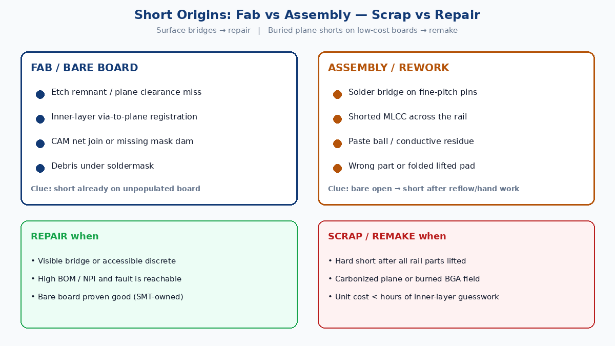
Scrap vs repair — practical call
Repair usually wins when:
- The bridge is visible on the surface or under a microscope
- A single discrete or connector is shorted
- The board is NPI / high BOM cost and the short is accessible
- You can prove the bare board was good (assembly-owned fault)
Scrap / remake usually wins when:
- Hard short remains after all rail discretes are lifted (inner layer / inaccessible)
- Multiple random bridges suggest systemic paste or stencil failure — fix process, don’t hero one board
- Carbonized laminate, blown planes, or heat-damaged BGAs after unlimited power abuse
- Unit cost is lower than hours of guesswork
Tell the fab or CM with evidence: ohms on bare vs assembled, photo of the bridge, thermal still, and which island isolation cleared the fault. That is CAPA language, not blame.
Prevention that reduces short scrap
Design / CAM
- Clearance and creepage for the working voltage; soldermask dams between fine-pitch pads
- DRC for accidental net joins; plane antipad sizes that survive registration tolerance
- Test points on rails for faster ohms triage
Assembly
- Stencil aperture and paste volume control; SPI on fine pitch
- AOI for bridges; X-ray on hidden joints when the package demands it
- Controlled rework — flux, tip size, and clean-up so you do not add bridges while fixing opens
IQC / lab — expect bare-board E-test on production lots, current-limited first power on new spins, and traveler fields for cold ohms plus the isolation step that cleared the short.
What this page is not
General circuit board repair, cold-solder joint triage, and “is this board bad” symptom trees cover opens, intermittent joints, and broad failure modes. Use those when the rail is not shorted. Use this page when continuity collapses between nets — especially power rails — and you need a safe, ordered path from DMM to isolate to thermal to rework or scrap.
Short finding is discipline, not drama: confirm cold, limit current if you bias, isolate until ohms move, fix the real bridge or part, and remake when the short lives inside the stackup.