
Before a China PCBA house releases the remaining boards in a lot, the first assembled unit — or a small first-piece sample built on the same stencil, feeders, programs, and reflow profile — must prove the setup matches the released BOM, polarity map, and solder/process gates. That checkpoint is PCBA First Article Inspection (FAI), also called first-piece verification. Skip it and one wrong reel, rotated CPL coordinate, or outdated BOM revision can stamp the same defect across every panel still in the queue. Pass it with a documented hold point and you only pay for the first-board debug — not a full-lot rework.
This note is a factory-floor FAI checklist for overseas buyers and engineers: BOM/revision lock, feeder and program setup, polarity, SPI/AOI/X-ray roles, power-up and functional gate, what belongs in the FAI report, and when to stop the lot. It is not a bare-board AOI or flying-probe primer, and it is not a design “does the schematic work” prototype review. FAI asks a different question: can this production setup build the released assembly correctly before we continue?
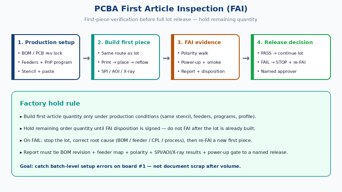
Hold the lot until the first piece clears
Treat FAI as a release gate, not a polite photo of a finished board. A usable purchase-order or traveler rule looks like this in practice:
| Decision | What it means on the floor |
|---|---|
| Build first-piece only | Assembly may load feeders and run the first board / panel under production conditions |
| Hold remaining quantity | No full-lot continuation until FAI disposition is signed |
| Fail → stop | Root cause, rework or scrap of the first piece, then re-FAI before restart |
| Pass → release | Named approval covers this BOM/PCB revision, line setup, and covered quantity |
Buyers who “FAI after the lot is done” are only documenting scrap. The hold belongs before the remaining quantity starts — after setup is real, before volume multiplies the error.
What FAI is — and what it is not
| Activity | Question it answers | Typical conditions |
|---|---|---|
| Design / EVT prototype | Does the circuit work? | May use hand place, temporary fixtures, engineering BOM |
| PCBA FAI (first piece) | Does production setup match released data? | Same stencil, paste, feeders, PnP program, reflow, inspection route as the lot |
| In-process AOI / SPI | Did this print or this placement look defective? | Machine gate on every board or sampled boards |
| Final lot inspection | Can we ship what we built? | After the authorized quantity is complete |
FAI can use SPI, AOI, X-ray, and a power-up bench — but those tools alone are not FAI. FAI is the configuration + evidence package that authorizes continuation.
Before the first board hits the printer
Most FAI failures are already living in the file pack. Lock these before paste hits the panel:
- PCB revision vs assembly revision — Gerber/ODB++ rev, silk markings, and assembly drawing must match the traveler.
- BOM / AVL freeze — MPN, value, package, ratings, DNP/DNI notes, and approved substitutes only. Unapproved alternates need a deviation, not a quiet feeder swap.
- Centroid / CPL orientation — Rotations and polarity flags vs assembly drawing and datasheet pin-1, especially connectors, diodes, LEDs, electrolytics, MOSFETs, and ambiguous QFN/BGA silk.
- Stencil identity — Aperture revision tied to this BOM/PCB pair; thermal-pad and fine-pitch windows match signed DFM notes.
- Customer kit reconciliation (consignment) — Count, moisture status, and reel labels matched to BOM lines before feeders are assigned.
If engineering notes and silkscreen disagree on pin 1, stop and resolve — do not pick the silk under schedule pressure.
Station checklist: setup through solder process
Build the first article on the production route, then verify by station. The goal is to catch batch-level setup errors, not to invent a unique craft process for board #1.
Feeder and program setup
| Check | Pass evidence |
|---|---|
| Reel / tray / tube ID vs BOM line | Photo or scan of label + feeder slot map |
| Feeder slot → reference designators | Line setup sheet matches PnP program |
| Nozzle / vision recipe for fine pitch | Program revision recorded |
| Panel orientation / fiducials | First pick alignment within process window |
| DNP lines empty | No phantom placements on do-not-populate refs |
Wrong-value and wrong-package escapes almost always start here: a lookalike 0402 reel in the wrong slot, or a substitute that shares footprint but not pinout.
SPI (solder paste inspection)
SPI is the pre-reflow gate. Confirm paste volume/area/height against the stencil recipe — especially under BGA/QFN thermal pads and fine-pitch leads. A first piece that fails SPI on critical pads should not proceed to place “just to see.” Fix print first.
Polarity and orientation gate
After place (and again after reflow where silk is readable), walk polar parts against the assembly drawing:
- IC pin 1 / chamfer / dimple vs silk and CPL rotation
- Diode / LED cathode marks
- Tantalum and aluminum electrolytic polarity
- MOSFET / regulator pinouts when silk is sparse
- USB, battery, board-to-board, and FFC/ZIF connectors — key and latch direction
Polarity errors often pass AOI if the body outline looks centered. They fail on power-up — sometimes by destroying the first article and the next boards if you already released the lot.
AOI after reflow
AOI owns visible placement and solder defects: missing parts, tombstones, lifts, bridges, skew, and polarity marks the camera is trained to see. Use a structured defect list tied to reference designators — not a green screenshot with no callouts. AOI does not clear hidden joints; treat “AOI pass” as necessary, not sufficient, when the BOM includes bottom-terminated packages.
X-ray for hidden joints
When the first article includes BGA, QFN/DFN, LGA, CSP, or other BTC packages, X-ray (2D or CT as agreed) belongs in the FAI scope for:
- Bridging under the package
- Opens / non-wet
- Excessive voiding on thermal pads (against the agreed criterion)
- Head-in-pillow indicators
- Gross misalignment
Record which packages were sampled and the acceptance rule. “We have an X-ray machine” is not a result; a named package list with pass/fail against criteria is.
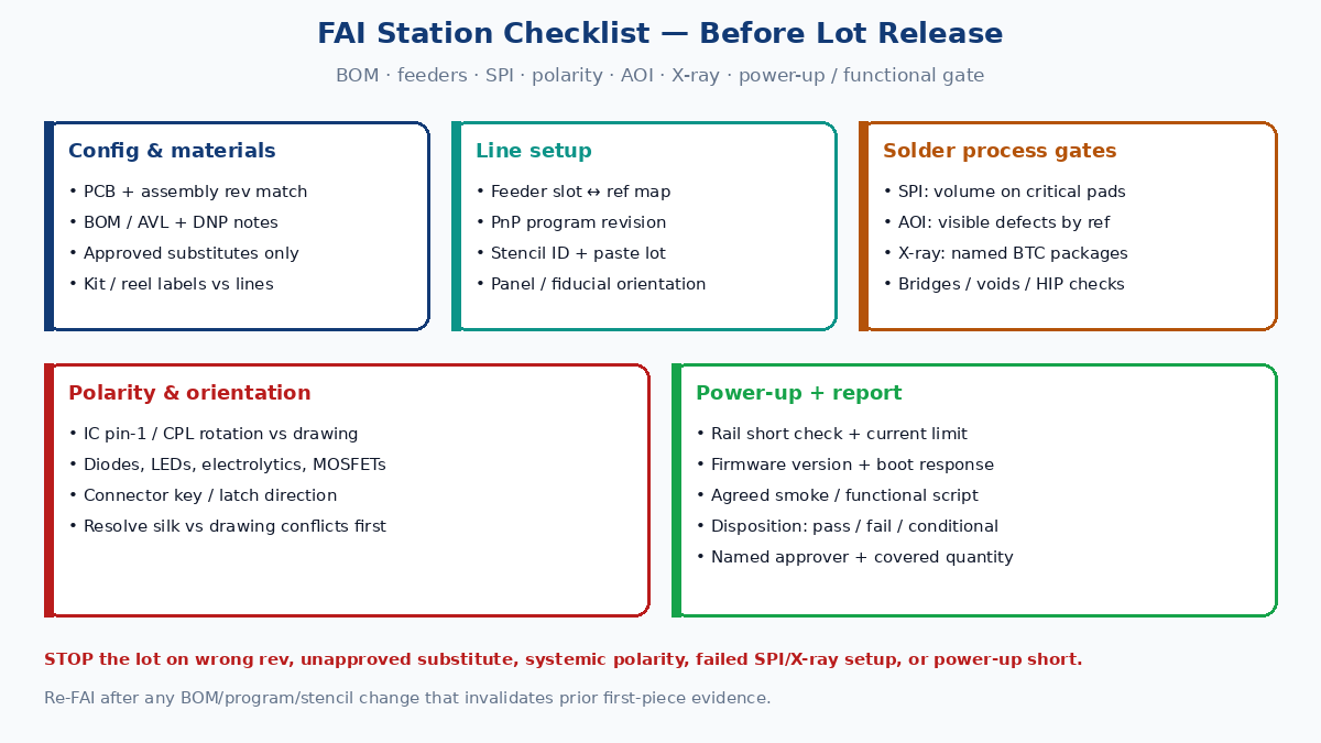
Power-up and functional gate
Visual and X-ray clearance still leave firmware mistakes, wrong-value passives in non-polar packages, and subtle assembly issues. Before releasing the lot:
- Safety first — Short check on major rails; correct input polarity; current-limited supply.
- Bring-up — Watch inrush and steady current; check for hot spots; verify key rail voltages.
- Program / boot (if required) — Correct firmware version, programming access, successful program, expected boot signature.
- Functional smoke — Run the agreed minimum bench script (interfaces, sensors, display, RF presence, drivers, charging — whatever proves “alive and correct”). A full FCT fixture is optional; a written smoke script is not.
No buyer test plan means the factory can only clear configuration and workmanship. If function matters before lot release, send the smoke script with the RFQ or NPI pack.
What belongs in the FAI report
A useful FAI package is a release record, not a marketing PDF. Minimum contents overseas buyers should expect:
| Section | Include |
|---|---|
| Identity | Customer PN, PCB rev, assembly rev, order / lot ID, first-article serial or panel ID, date, line / equipment ID |
| Configuration | BOM rev + AVL note, stencil ID, PnP program rev, reflow profile ID, inspection program revs |
| Materials | Key component lot / date codes where required; paste lot; any approved substitute used on the first piece |
| Setup evidence | Feeder map or checklist sign-off; photo of critical polarity parts if agreed |
| Process / inspection | SPI summary on first panel; AOI defect list (even if zero); X-ray results for named BTCs |
| Electrical / functional | Power-up limits used, rail checks, firmware version, smoke-test results |
| Discrepancies | NCRs, rework performed on the first piece, open deviations with owner |
| Disposition | Pass / fail / conditional; named approver; quantity authorized to continue; expiry or change triggers |
Conditional pass only works when the condition is explicit (e.g., “lot may continue after X-ray sampling plan A on every panel”). Vague “approved with comments” without owners is how stops get ignored.
When to stop the lot — and when to re-FAI
Stop immediately if the first article shows:
- Wrong PCB or BOM revision
- Unapproved substitute or wrong MPN on any line
- Systemic polarity / CPL rotation error
- Stencil or paste process that fails SPI on critical apertures
- BTC solder defects that indicate profile / paste / placement setup issues
- Power-up short, wrong rail, or functional fail tied to assembly (not an open design bug under engineering investigation)
Correct the root cause, rebuild or rework per agreement, and run FAI again on a new first piece built after the fix. Do not “inspect harder” on the remaining boards while leaving the bad feeder loaded.
Re-FAI or delta-FAI when prior evidence no longer covers the build: PCB or BOM/AVL revision, new substitute MPN, stencil/program/line move, a long interruption or material-lot change called out in your quality agreement, or first production after a hand-build prototype phase. Delta scope may cover only changed characteristics when the contract allows — still document what is covered vs inherited.
Buyer language that makes FAI enforceable
Put the hold in writing:
- “Supplier may build first-article quantity only (state N boards or 1 panel). Remaining order quantity shall not start until buyer or designated SQE signs FAI disposition.”
- “FAI shall include BOM-to-board verification, polarity of all polarized parts, AOI on first article, X-ray on listed BTC packages, and the attached power-up / smoke script.”
- “Any unapproved substitute used on FAI requires written deviation before lot release.”
Attach released BOM/AVL, assembly drawing, centroid file, smoke script, and the BTC X-ray list. Quotes without those attachments are not quoting the same job.
Practical takeaway
PCBA FAI is full-lot insurance on a China assembly order: one controlled first piece, built like production, checked against BOM revision, feeder/program setup, polarity, SPI/AOI/X-ray roles, and a power-up gate — then a written stop-or-go. Demand the report fields above and keep the remaining quantity on hold until disposition is signed.