
Rigid-flex boards often pass flat electrical test and then open after fold-in, connector mating, or a few hundred hinge cycles. The crack is rarely “mystery copper.” It is usually a stress concentration you can name: radius vs stackup, vias at the transition, stiffener edge, coverlay opening, I-beam copper, or moisture-driven delamination. This note is a failure-analysis map for overseas engineers diagnosing bend cracks — root cause → DFM prevention table → RFQ clues that keep a China fab from guessing the fold. It is not a bend-radius-only primer and not a bookbinder construction guide; those live elsewhere. Here the job is diagnosis and prevention.
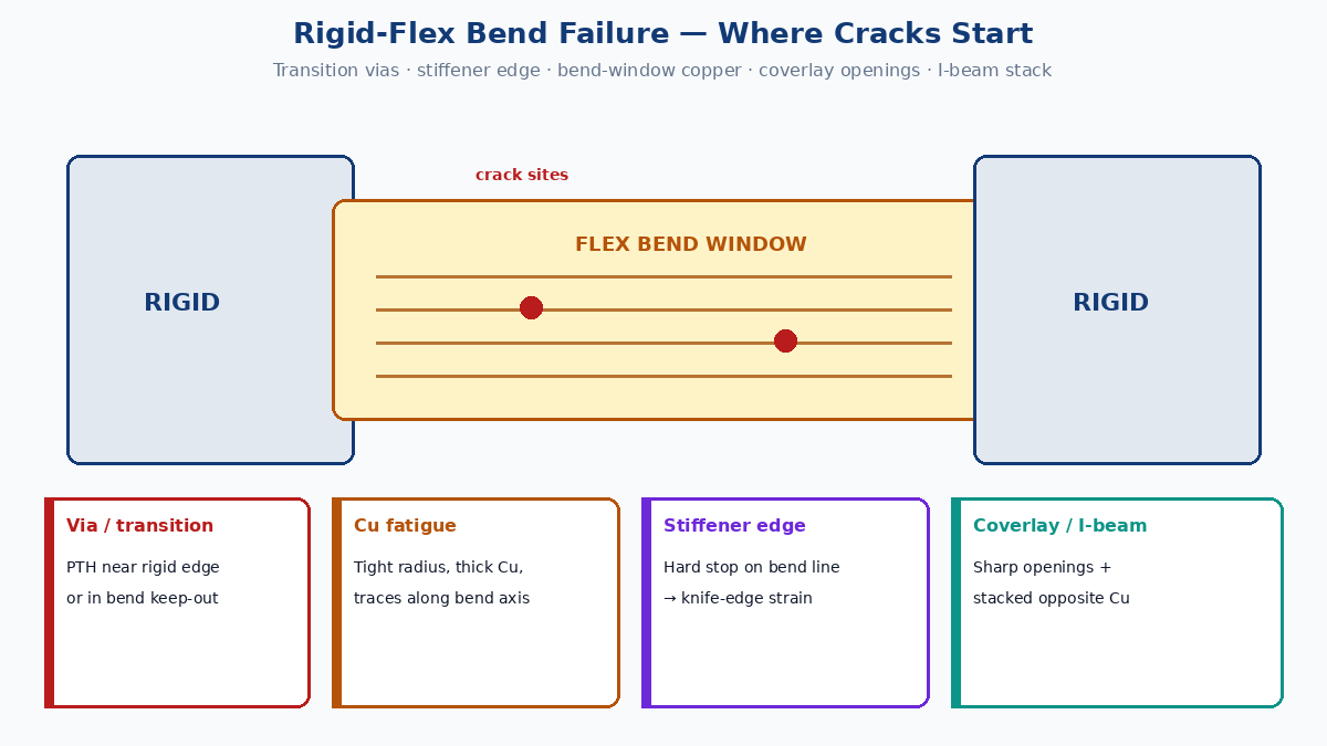
Quick answer: why rigid-flex bends crack
Most field and prototype bend failures cluster into seven modes:
- Copper fatigue / trace crack — radius too tight for copper thickness and layer count, sharp corners, or traces running along the bend axis.
- Via / barrel crack — plated holes inside or next to the active bend or rigid-to-flex transition.
- Pad lift — unsupported pads or connectors on flex without a stiffener, or coverlay openings that leave copper floating.
- Stiffener-edge stress — polyimide / FR-4 / stainless stiffener ending exactly where the fold starts, creating a knife-edge.
- Coverlay opening stress — sharp, oversized, or poorly overlapped openings in the bend window.
- I-beam effect — copper on opposite flex layers stacked in register, stiffening the section like a beam.
- Delamination — moisture, abrupt thickness step, weak coverlay/bondply overlap, or thermal shock at the transition.
A board can be electrically perfect on a flat bed and still fail the first install fold. Treat bend reliability as a mechanical + stackup review, not a late “make the radius bigger” tweak.
💡 Factory gain: State flex-to-install vs dynamic flex, bend direction, min radius, stiffener outline, and via keep-out from the bend line in the fab notes. Gerbers alone do not show the fold.
Flex-to-install vs dynamic flex (diagnosis first)
Before you chase process scrap, lock the use case. The same stackup can survive one install fold and fail under cyclic motion.
| Use | What fails first | Design posture |
|---|---|---|
| Flex-to-install | Install over-bend, transition vias, stiffener edge, enclosure interference | Confirm final folded shape, direction, and one-time strain |
| Dynamic flex | Copper fatigue, I-beam stiffness, multilayer flex thickness | Fewer flex layers, thinner copper, staggered traces, larger radius, fatigue-aware materials |
If the product is a hinge, printer head, or robot joint, do not reuse “install-only” radius folklore. Confirm the duty cycle with the fab against your stackup — typical industry starting guidance often cites roughly 10× dielectric thickness for one-time flex and ~20× for dynamic flex as a planning ballpark, not a guaranteed capability. Always verify against the released stackup and copper weight.
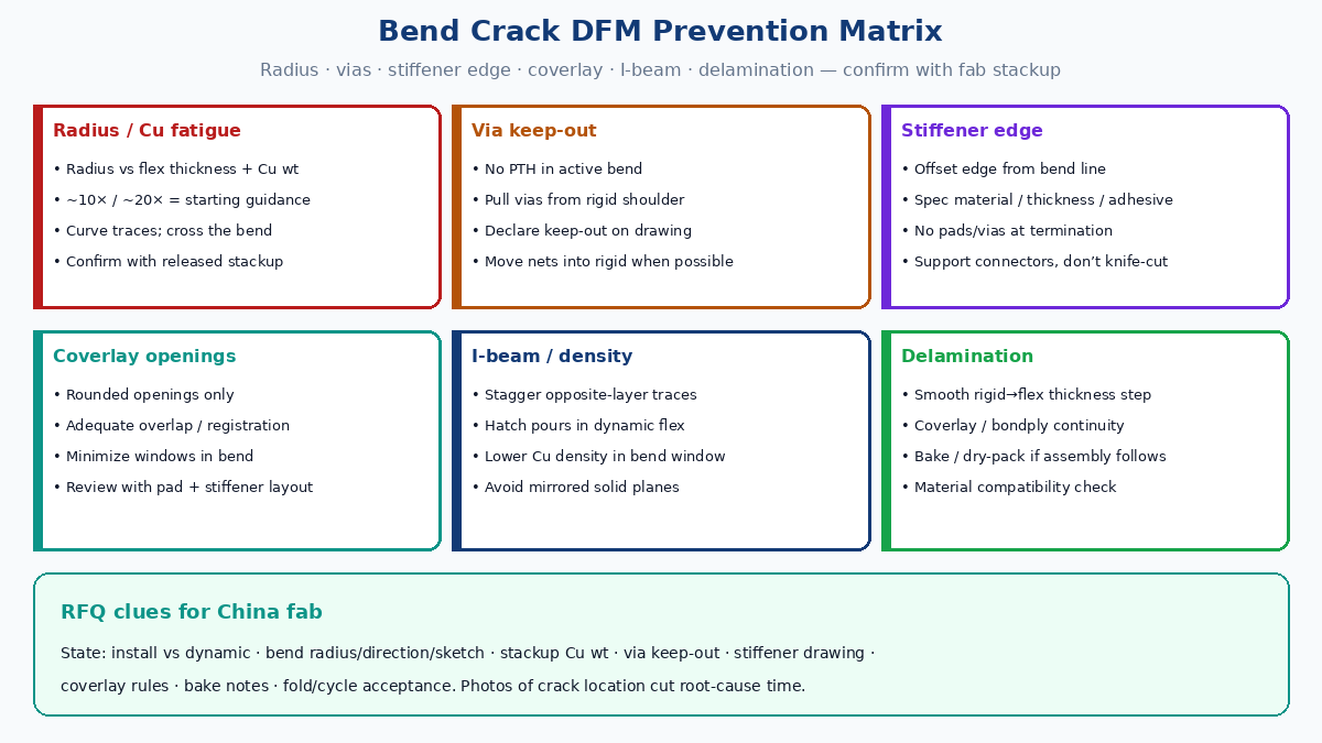
Failure-mode → root cause → DFM prevention
Use this table when a unit fails after fold or after bend cycling. Match the symptom location before you change copper weight globally.
| Failure mode | What you see | Root cause (typical) | DFM prevention |
|---|---|---|---|
| Copper trace crack | Open or intermittent in bend window; crack across trace | Radius too small; thick Cu; sharp corners; traces parallel to bend axis; solid planes | Larger radius vs stackup; thinner Cu in flex; curved routing; cross the bend when possible; reduce plane density |
| Via / barrel crack | Opens near transition or under microscope at PTH | Via in bend or within stress keep-out of rigid edge | Move vias into rigid or non-bend flex; define keep-out from bend line and rigid edge |
| Pad lift | Pad peels under connector force or bend | No stiffener; oversized coverlay opening; pad on unsupported flex | Stiffener under connectors; rounded coverlay openings; keep pads out of active bend |
| Stiffener-edge crack | Crack / delam at stiffener termination | Stiffener edge on bend line; abrupt stiffness step | Offset stiffener edge from bend; avoid vias/pads at edge; smooth transition |
| Coverlay stress | Tear or copper fatigue at opening corner | Sharp opening corners; weak overlap; exposed Cu in bend | Rounded openings; adequate overlap / registration; minimize openings in bend |
| I-beam fatigue | Early fatigue despite “OK” radius | Opposite-layer Cu stacked; dense Cu both sides | Stagger traces; hatch planes; lower Cu density in bend |
| Delamination | Layer split at transition or after reflow/fold | Moisture; abrupt thickness; poor bondply/coverlay; material mismatch | Pre-bake / dry pack rules; smooth transition; review coverlay/bondply; confirm stack compatibility |
How to read the failure on the bench
Crack across copper in the free bend — start with radius vs flex thickness and copper weight, then check routing geometry and I-beam stacking. Cross-sections of the flex often show work-hardened copper with little dielectric tear.
Open near the rigid edge with vias present — treat as transition-zone stress. Move or delete vias; pull the bend line away from the rigid shoulder; check for sharp outline corners at the transition.
Failure exactly at a stiffener tip — the stiffener is doing its job as a hard stop. Relocate the edge, change thickness/material callout, and keep copper features off that line.
Intermittent after humidity + reflow + fold — add delamination and moisture to the list. Ask for bake notes, packing, and whether the transition has adequate coverlay/bondply overlap.
Passes install, fails after N cycles — dynamic fatigue. Revisit layer count, copper weight, stagger, and whether the enclosure forces a tighter radius than the drawing.
Rigid-to-flex transition: the usual crime scene
Many “mystery” cracks start where stiffness jumps. Abrupt thickness change, vias hugging the rigid edge, copper neck-down, stiffener termination, and a bend line drawn too close to the shoulder all pile strain into a few mils of copper.
Practical checks before CAM:
- Mark rigid vs flex outlines and bend line / bend direction on a mechanical drawing.
- Keep vias, pads, and heavy copper out of a declared keep-out from the transition.
- Avoid sharp internal corners on the flex outline at the shoulder.
- Align coverlay and bondply so the flexible stack is continuous through the bend, not notched at the edge.
- Confirm enclosure clearance so assembly cannot force a tighter fold than designed.
Electrical-only Gerber review misses most of this. Fold geometry is a deliverable, not optional art.
Coverlay, stiffener, and copper density details that scrap prototypes
Coverlay — rounded openings, enough overlap for registration, and no large windows sitting in the bend. Sharp rectangular openings act like tear starters.
Stiffener — call out material, thickness, adhesive, and outline. A stiffener under a ZIF/FFC or board-to-board connector is often mandatory; the failure mode without it is pad lift or connector tear-out, not “bad plating.”
Copper density — solid pours and mirrored traces turn the flex into a beam. Stagger layer-to-layer, prefer hatched pours in dynamic regions, and keep critical nets nearer the low-strain region of a balanced stack when the layer count allows.
Neutral axis — extra dielectric or unbalanced copper moves conductors into tension/compression. Multilayer flex in a dynamic hinge is a common overbuild: more layers “for routing” that the hinge cannot afford.
China-fab RFQ clues that speed diagnosis (and prevent the next crack)
Factories cannot invent your fold from Gerbers. Incomplete RFQs produce polite clarification loops — or a build that only works flat.
Put these in the zip or cover note:
| RFQ field | Why it matters |
|---|---|
| Flex-to-install vs dynamic + expected cycles | Sets radius / layer / Cu posture |
| Bend radius, angle, direction, final folded sketch | Prevents enclosure over-bend |
| Stackup with flex Cu weight and flex layer count | Radius guidance is stackup-relative |
| Via keep-out from bend line / rigid edge | Stops PTH in the strain zone |
| Stiffener drawing (material, thickness, edge location) | Avoids knife-edge at fold |
| Coverlay opening rules in bend window | Reduces tear starters |
| Bake / dry-pack / moisture notes if assembly follows | Cuts transition delam risk |
| Acceptance: fold test, cycle count, or microsection | Aligns inspection to the failure you fear |
If you already have cracked units, send photos of the crack location, whether failure was first fold or after cycling, and whether the board saw reflow/humidity. That shortens root-cause from weeks of email to a stackup/layout change list.
Common design mistakes that look like “fab defects”
- Treating rigid-flex like a rigid board with a soft middle — no mechanical drawing.
- Shipping Gerbers only — no bend direction, no stiffener, no folded outline.
- Leaving vias “just inside” the flex for routing convenience.
- Over-layering the flex “because we had the space.”
- Ignoring coverlay and stiffener as CAM defaults.
- Passing flat ICT/flying probe and calling the design proven without a fold or cycle check.
None of these require exotic materials to fix. They require stating the mechanical intent before lamination.
Closing
Rigid-flex bend cracks are usually predictable stress concentrations: radius vs stackup, transition vias, stiffener edges, coverlay openings, I-beam copper, and delamination drivers. Map symptom → mode → DFM change, then put bend geometry and keep-outs in the RFQ so the fab is not reverse-engineering your enclosure. For construction styles and bend-reliability architecture, use the dedicated rigid-flex reliability notes on this site; use this page when you are diagnosing why a crack appeared and what to change before the next spin.