
Rigid-flex designs fail less often from exotic materials than from layout decisions made before the stackup and fold are locked. Overseas engineers usually search for bend-radius folklore after Gerbers are done. This page is the opposite: a preventive DFM checklist you run before routing — static vs dynamic, bend keepout, via setback, perpendicular routing, transition/step stack, copper balance — plus what belongs on the fab drawing for a China RFQ. It is not a bend-crack autopsy and not a bookbinder construction note; those live elsewhere. Here the job is design rules before you order.
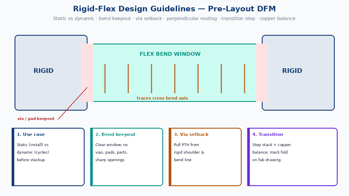
Quick answer: rigid-flex DFM before layout
Lock these six items before you place copper in the flex window:
- Static vs dynamic use — one-time install fold vs cyclic motion; this drives layer count, copper weight, and radius posture.
- Bend keepout — no vias, pads, components, or sharp coverlay openings in the active bend.
- Via setback — pull plated holes away from the bend line and the rigid-to-flex shoulder.
- Perpendicular routing — cross the bend axis; curves and gradual widths, not 90° corners.
- Transition / step stack — smooth thickness change, continuous coverlay/bondply, stiffener edge off the fold.
- Copper balance — stagger opposite layers, hatch pours, avoid I-beam stacking in the bend.
Radius “multipliers” are typical planning guidance only. Confirm every number against your released stackup, copper weight, and fab capability — never treat a blog ratio as a guaranteed fab limit.
💡 Factory gain: Put bend direction, folded sketch, via keep-out, stiffener outline, and install-vs-dynamic on the mechanical drawing. Electrical Gerbers alone do not describe the fold a China fab must build to.
Static vs dynamic: decide before stackup
| Use | What “good” looks like | Design posture |
|---|---|---|
| Static (flex-to-install) | Board folds once into the enclosure and stays | Radius can be tighter for that stackup; still keep vias/pads out of the fold |
| Dynamic | Hinge, printer head, robot joint, door, scanner | Fewer flex layers, thinner copper, larger radius, staggered traces, fatigue-aware materials |
If the product moves every power cycle, do not reuse an “install-only” stackup and hope the radius note saves you. Write the duty cycle (install once / expected cycles) on the fab drawing so CAM does not assume the wrong class of flex.
Industry planning often starts around roughly ~10× flex dielectric thickness for one-time flex-to-install and about ~20× for dynamic flex as a ballpark — not a capability claim. Multilayer dynamic flex usually needs a more conservative posture and fab review. Always verify against thickness, copper weight, and layer count on your stackup.
Bend keepout: empty space is a reliability feature
Treat the active bend window as a mechanical zone, not leftover routing real estate.
Keep out of the bend:
- Vias and plated through-holes
- Pads and components
- Abrupt copper widenings and solid mirrored planes
- Sharp rectangular coverlay openings
Mark on the drawing: bend line, bend direction, bend angle or fold sketch, and the keepout boundary. If enclosure clearance forces a tighter fold than the drawing, fix the enclosure or the radius — do not leave it as tribal knowledge for assembly.
Coverlay openings that must exist near connectors should stay outside the active bend, use rounded corners, and keep enough overlap for registration. Sharp openings in the bend act as tear starters even when electrical clearance looks fine.
Via setback from bend and rigid shoulder
Plated holes are stiff points. Strain that should distribute through polyimide and copper concentrates at the barrel and pad entry.
Practical DFM:
- No PTH in the active bend window.
- Pull vias back from the rigid-to-flex transition (the shoulder), not just from the geometric center of the fold.
- Prefer routing that lands vias in rigid sections when the net allows.
- Declare a via keep-out dimension on the fab drawing so CAM and DRC share the same rule.
Exact setback mils depend on stackup, outline radius at the transition, and fab process. Put a number on the drawing after fab alignment; do not leave “keep vias away” as a verbal note.
Route for bending: perpendicular, curved, gradual
In rigid areas you optimize density and SI. In the bend window you optimize strain distribution.
| Practice | Why |
|---|---|
| Route traces perpendicular to the bend axis when possible | Spreads strain across the conductor length |
| Prefer curves over 90° corners | Corners are stress concentrators under fold |
| Avoid sudden neck-downs | Width steps localize fatigue |
| Split very wide traces if needed | Wide solid copper stiffens the section |
| Stagger traces on opposite flex layers | Reduces I-beam stiffness |
Parallel-to-bend routing, mirrored copper, and sharp corners are common reasons a board passes flat electrical test and opens on first install. Fix geometry in CAD; do not expect plating magic to absorb bad routing.
Transition zone and step stack
The rigid-to-flex transition is where stiffness jumps. Abrupt thickness change, vias hugging the edge, copper neck-down, and a stiffener ending on the bend line pile strain into a few mils of copper.
Pre-CAM checks:
- Smooth the thickness step (coverlay / bondply / selective dielectric) so the flex stack is continuous through the bend.
- Avoid sharp internal corners on the flex outline at the shoulder.
- Offset stiffener edges from the bend line; call out material, thickness, and adhesive. Stiffeners support connectors — they should not become a knife-edge on the fold.
- Align coverlay and bondply so the flexible region is not notched at the rigid edge.
- Confirm enclosure clearance matches the designed radius and direction.
Electrical-only Gerber review misses most of this. Fold geometry is a deliverable.
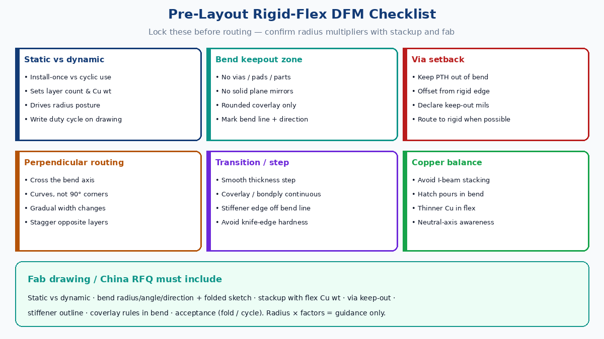
Copper balance and I-beam control
Copper density in the bend window is a mechanical design choice.
- I-beam effect — copper on opposite layers stacked in register turns the flex into a stiff beam. Stagger traces layer-to-layer.
- Solid pours — prefer hatched or reduced copper in dynamic regions.
- Copper weight — thinner copper in the flex generally tolerates bending better than heavy foils; confirm with the stackup, not with a global “use 1 oz everywhere” habit.
- Neutral axis — unbalanced dielectric or copper moves conductors into tension or compression. Extra flex layers “for routing” often cost more bend life than they buy in channel count.
If you need planes for EMI in the flex, hatch them in the bend window and keep solid pours in rigid or non-bend flex.
Pre-layout checklist (run before routing the flex)
Use this as a gate before detailed bend-window routing:
| # | Gate | Pass criteria |
|---|---|---|
| 1 | Use case | Static vs dynamic written; expected cycles if dynamic |
| 2 | Stackup | Flex layer count + Cu weight agreed with fab |
| 3 | Radius | Starting radius vs thickness confirmed with stackup (multipliers = guidance only) |
| 4 | Bend keepout | Window drawn; no parts/vias/pads planned inside |
| 5 | Via setback | Keep-out from bend line and rigid shoulder declared |
| 6 | Routing rules | Perpendicular preference, curves, stagger, no sharp necks |
| 7 | Transition | Step stack, coverlay continuity, stiffener edge offset |
| 8 | Copper balance | No mirrored solid stacks; hatch plan for bend pours |
| 9 | Fab drawing | Fold sketch, direction, stiffener, acceptance notes |
Skip the gate and you are designing a failure autopsy into the next spin.
What to put on the fab drawing for a China RFQ
Factories cannot invent your enclosure fold from copper layers alone. Incomplete RFQs produce clarification loops — or a board that only works flat.
| Drawing / RFQ field | Why it matters |
|---|---|
| Static vs dynamic + expected cycles | Sets radius / layer / Cu posture |
| Bend radius, angle, direction, folded sketch | Prevents enclosure over-bend |
| Stackup with flex Cu weight and flex layer count | Radius guidance is stackup-relative |
| Via keep-out from bend line / rigid edge | Stops PTH in the strain zone |
| Stiffener drawing (material, thickness, edge location) | Avoids knife-edge at fold |
| Coverlay opening rules in bend window | Reduces tear starters |
| Bake / dry-pack notes if assembly follows | Cuts transition moisture risk |
| Acceptance: fold test, cycle count, or microsection | Aligns inspection to the risk you designed for |
Ship mechanical + stackup + Gerbers together. A zip of copper layers with “rigid-flex, please advise radius” is not a DFM package.
Common pre-layout mistakes that look like fab defects later
- Choosing layer count before defining motion type.
- Setting bend radius from enclosure space only, then asking fab to “make it work.”
- Routing sharp corners and parallel traces through the bend for density.
- Parking vias just inside the flex for routing convenience.
- Ending a stiffener on the bend line.
- Leaving coverlay and stiffener as CAM defaults with no drawing callouts.
- Passing flat ICT/flying probe and calling the design proven without a fold check.
None of these require exotic materials to fix. They require stating mechanical intent before lamination.
Closing
Rigid-flex reliability is decided in pre-layout DFM: static vs dynamic, bend keepout, via setback, perpendicular routing, transition/step stack, and copper balance — then written onto the fab drawing so a China fab builds the fold you designed. Use this page when you are still able to change the layout. For diagnosing cracks that already appeared, and for specialized construction styles, use the dedicated failure-analysis and reliability notes on this site; use this page to prevent those cracks before you order.