
A flex PCB (FPC) connector tail for a ZIF or FFC-style receptacle fails first on finished reinforced thickness, pad geometry, and insertion mechanics — not on a generic “flex quality” line item. Too thick and the latch will not close or contacts ride high; too thin and contact force collapses into intermittents. Pad pitch, contact side, coverlay openings, and stiffener edge location decide whether the first mate survives NPI or scrap starts at the connector. Start every RFQ from the connector datasheet, not from a habit thickness.
This China-fab DFM note covers ZIF / LIF / FFC / FPC tails only: datasheet-driven thickness, stiffener and bend keep-outs, pads / coverlay / gold finish, failure modes, and fast-turn traps when the datasheet is missing. It is not a dynamic-bend via article, not an EMI shield note, and not a general flex materials survey.
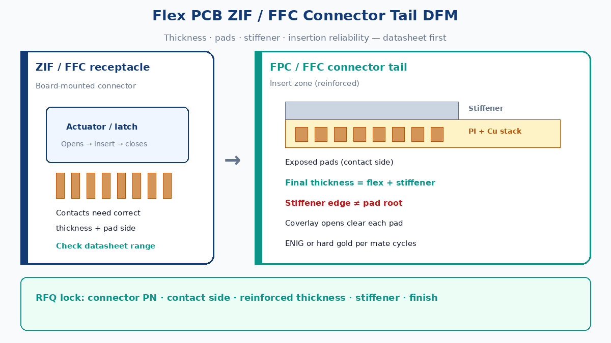
Answer first: pad, thickness, insertion reliability
| Question | Factory / procurement answer |
|---|---|
| What is a connector tail? | The stiffened end of an FPC (or FFC) that inserts into a ZIF / LIF / FFC receptacle — pads, coverlay openings, and reinforcement in one zone |
| Why does it fail first? | Insertion force, latch travel, and contact wipe are absolute; the rest of the flex can be perfect and the mate still rejects |
| Thickness rule | Match the connector’s specified total thickness at the insert zone — PI + Cu + coverlay + adhesive + stiffener. Do not invent a universal mm number |
| Pad rule | Pitch, pad width/length, and contact side (same side as stiffener or opposite) must match the PN drawing |
| Finish rule | Many ZIF/FFC systems expect gold on exposed pads; ENIG vs hard gold is a datasheet / cycle-life call, not a catalog preference |
| RFQ minimum | Connector PN, contact side, final reinforced thickness target + tolerance, stiffener material and side, surface finish |
💡 Factory gain: Put connector PN + contact side + final reinforced thickness + stiffener stack on the traveler before CAM prices “standard flex.” Missing those five fields is the #1 fast-turn delay on connector tails.
Why connector tails are critical
The tail is where electrical contact, mechanical latching, and fab stackup collide in a few millimeters:
- Contact force window — ZIF/LIF springs are designed for a narrow thickness and pad height. Outside that window you get no latch, overstress, or intermittent wipe.
- One-shot insertion at NPI — First-article mating is often the first real test. A thickness miss shows up as “won’t insert” on the bench, not as a netlist error in CAM.
- Crack path at the stiffener edge — The stiffener ends where the flex must still bend into the housing. Misplaced stiffener edge relative to the pad root is a classic tear / copper crack starter.
- Fine-pitch coverlay registration — At 0.5 mm and finer pitches, coverlay open mis-registration shorts adjacent pads or leaves copper under film (no wipe).
Buyers who treat the tail as “just the end of the flex” under-specify the only zone the connector cares about.
ZIF, LIF, FFC, FPC — what the words mean on the floor
| Term | Meaning in procurement / fab talk | Tail implication |
|---|---|---|
| FFC | Flat Flexible Cable — usually laminated conductors in a film cable, often commodity pitch | Tail geometry often standardized; still needs thickness and stiffener per connector |
| FPC | Flexible Printed Circuit — etched Cu on PI, custom routing | Tail is designed: pad pattern, contact side, stack, and stiffener are drawing callouts |
| ZIF | Zero Insertion Force — actuator/latch opens contacts for insert, then closes | Thickness and pad alignment must allow latch travel; force after latch, not during insert |
| LIF | Low Insertion Force — lighter spring; still needs correct thickness | Over-thick tails can damage contacts even at “low” force |
| FFC connector | Receptacle family that accepts FFC or FPC tails meeting the same insert spec | Spec is mechanical + plating + pitch — construction name (FFC vs FPC) is secondary |
An FPC tail for a ZIF/FFC connector is successful when it behaves like the cable the connector was qualified against in the insert zone: pitch, pad length, contact side, reinforced thickness, and finish.
Start with the datasheet (not a thickness habit)
Before Gerbers leave engineering, extract from the connector manufacturer datasheet / drawing:
| Datasheet field | What to lock on the fab drawing |
|---|---|
| Pitch / pin count | Pad pitch, pad count, outline width |
| Recommended FPC/FFC thickness | Final insert-zone thickness (often a range). Check the datasheet — do not paste a remembered number |
| Contact / exposed side | Which face of the flex has open pads vs stiffener |
| Pad length into the connector | Exposed pad length past coverlay; insertion depth marks if required |
| Stiffener recommendation | Material (PI, FR-4, metal), thickness contribution, which side |
| Actuator / latch type | Front-flip, back-flip, slide — affects how thick the leading edge can be |
| Plating | Gold thickness / type expectations for mating cycles |
| Temperature / retention | Retention force and temp range for stiffener adhesive choice |
Procurement tip: Attach the connector PDF (or the thickness + pad page) to the RFQ. Quotes without that attachment are not comparable — Plant A will assume one thickness family, Plant B another.
Thickness tolerance — too thick vs too thin
Finished reinforced thickness = flex stack in the insert zone plus stiffener (and adhesive). Coverlay openings do not remove copper thickness under pads; they remove the dielectric over the wipe area.
| Condition | What happens at mate | Factory / test symptom |
|---|---|---|
| Too thick | Latch will not close; contacts ride high; housing binds | “Won’t insert” / actuator won’t lock; possible contact plastic set |
| Too thin | Contact force low; wipe incomplete | Intermittent opens, high contact resistance, fails continuity under vibration |
| Thickness OK, pad side wrong | Contacts face film or stiffener | Zero continuity on first mate — looks like a fab “open,” is a design side error |
| Thickness OK, stiffener short | Leading edge soft / buckles | Crumple on insert; pad scuff; incomplete depth |
| Thickness OK, stiffener long into bend | Tail cannot form into housing | Crack at stiffener edge; copper lift at pad root |
Tolerance comes from the datasheet range and the fab’s stack-up capability (PI, Cu, adhesive, coverlay, stiffener). Ask the fab to confirm measured final thickness on first articles in the insert zone — not only raw laminate thickness.
⚠️ No universal mm rule: Connector families differ. Always use the thickness (or thickness range) printed for that PN. Copying a thickness from a previous project is a common fast-turn scrap cause.
Stiffener and bend keep-out
Stiffener exists so the insert zone is rigid enough to push straight into the receptacle. Everything immediately behind that zone must still flex.
| Callout | Why it matters |
|---|---|
| Stiffener material | PI film, FR-4, or metal — each adds different thickness and edge sharpness |
| Stiffener side | Same side as pads or opposite — must match contact-side definition |
| Stiffener edge vs pad root | Edge too close to pad root → peel / crack under insert and latch force |
| Bend / form keep-out | Region between stiffener end and any component or tight radius — no vias, no abrupt coverlay steps if the tail must form |
| Leading-edge chamfer / taper | Some drawings call a soft entry; square thick edges snag actuators |
Crack path (factory): Insert force and latch clamp load the pads. If the stiffener edge sits at or just behind the pad root, copper and coverlay see a sharp stiffness step. Fatigue or first-insert tear starts there — often mis-diagnosed as “bad coverlay adhesion.”
Mark on the fab drawing: stiffener outline, material, thickness, side, adhesive type if critical, and a keep-out from stiffener edge to first bend or component.
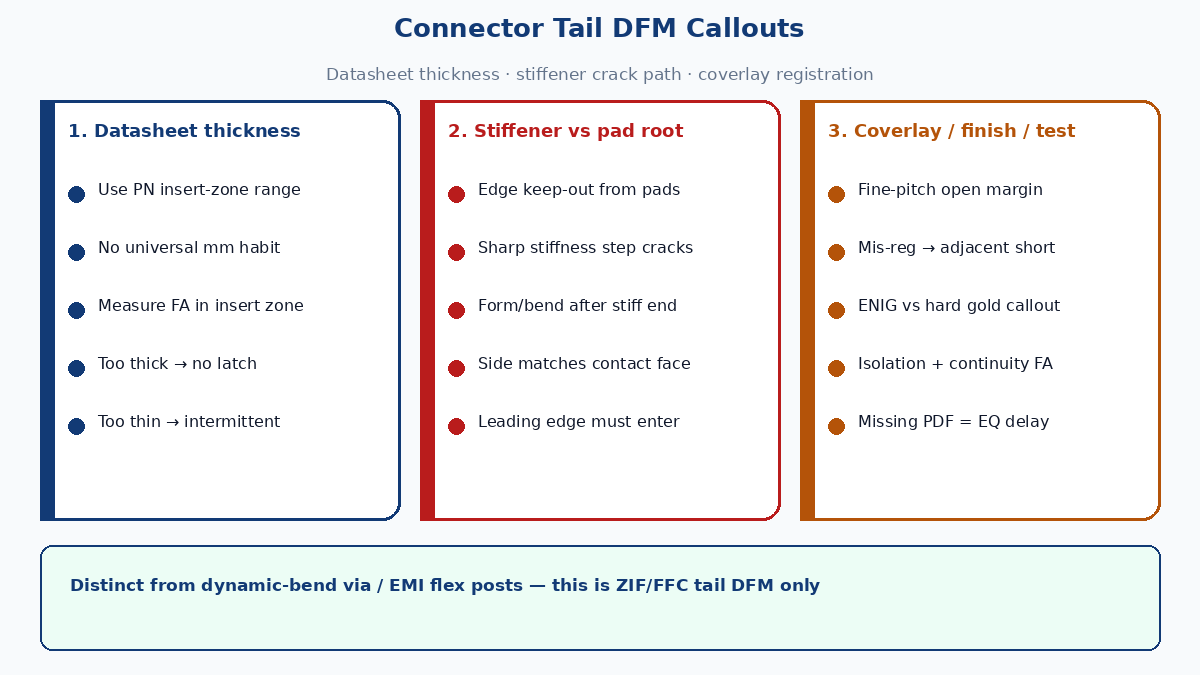
Pads, coverlay, and gold finish
| Item | DFM / test note |
|---|---|
| Pad pitch / width | Match connector drawing; undersize pads lose wipe area; oversize risk short under coverlay mis-reg |
| Exposed pad length | Enough for full contact wipe at nominal insert depth |
| Coverlay opening | Opens must clear each pad with registration margin; fine pitch → coverlay-to-pad clearance is a test item (shorts / opens) |
| Coverlay registration | Mis-reg → copper bridge under film or film over wipe zone |
| ENIG | Common fab finish; verify Au thickness / Ni barrier meet connector mating guidance |
| Hard gold (electrolytic) | Often preferred for higher mate cycles; call out explicitly — not the same traveler as ENIG |
| OSP / bare Cu | Usually wrong for ZIF/FFC wipe contacts unless the datasheet allows it |
Testing / factory gain: On fine-pitch tails, add a coverlay registration check (optical or fixture continuity between adjacent pads) before ship. Shorts from coverlay squeeze-out or mis-open are not caught by netlist alone.
Failure modes checklist (tail-only)
| Failure | Likely cause | Who catches it |
|---|---|---|
| Will not insert / latch | Over-thickness; wrong stiffener; leading edge too blunt | Assembly / NPI |
| Intermittent contact | Under-thickness; wrong contact side; gold thin / contaminated | Test / field |
| Adjacent pad short | Coverlay mis-registration; residue; oversize pads | Hi-pot / isolation test |
| Open on one pin | Coverlay over pad; incomplete etch; scratched pad on insert | Continuity |
| Copper crack at pad root | Stiffener edge too close; bend into housing against stiff edge | Visual / flex after mate |
| Latch damage | Repeated force-insert of over-thick tail | Connector scrap (expensive) |
Fast-turn risks when the datasheet is missing
Fast-turn flex is only fast when the insert zone is fully specified. Missing datasheet fields create EQ loops that burn the “quick turn” calendar:
| Missing input | What the fab does | Delay / scrap pattern |
|---|---|---|
| No connector PN | Guesses pitch from Gerber only | Wrong contact side or pad length |
| No final thickness | Quotes “standard stiffener” | First articles too thick or thin |
| No stiffener side | Defaults to shop habit | Pads face wrong way → full respin |
| No finish callout | Defaults to ENIG | Mate-cycle or wipe mismatch |
| Thickness “same as last job” | Copies old stack | New PN has different window → NPI fail |
Procurement gain: Block the RFQ until connector PN, contact side, final reinforced thickness (from datasheet), stiffener material/side, and finish (ENIG vs hard gold) are on one line. That five-field lock prevents the most common connector-tail respin.
FPC vs FFC vs rigid-flex (for this interface)
| Construction | When it fits a ZIF/FFC interface | Watch-outs |
|---|---|---|
| FFC | Straight pitch cable, no custom circuit in the span | Limited routing; still needs correct stiffener/thickness |
| FPC | Custom routing, branches, components near the tail | Full DFM on pads, coverlay, stiffener, and form keep-out |
| Rigid-flex | Rigid zones carry parts; flex span ends in a ZIF tail | Tail zone still follows connector thickness rules; rigid area ≠ insert thickness |
Do not assume a rigid-flex “standard stack” automatically meets the receptacle thickness — the insert zone stack is what the connector sees.
Typical applications
Connector tails show up wherever a flex or cable must mate into a board-mounted ZIF/FFC receptacle:
- Display / camera / touch flexes into main boards
- Wearables and compact consumer modules
- Medical and industrial handhelds with replaceable flex harnesses
- Printers, scanners, and mechanisms that need a serviceable FFC/FPC link
In every case the reliability story is the same: datasheet thickness + pad/contact-side correctness + stiffener edge control + coverlay registration + finish that matches mate cycles.
RFQ line that makes quotes comparable
Copy into the RFQ / fab notes:
- Connector manufacturer + PN (attach datasheet page for thickness / pads)
- Contact / exposed pad side relative to stiffener
- Final reinforced thickness target and tolerance (from datasheet — not a remembered universal)
- Stiffener material, thickness contribution, side, edge keep-out from pad root
- Surface finish: ENIG or hard gold (and Au requirement if specified)
- Pitch, pin count, pad length, coverlay open notes
- First-article: measure insert-zone thickness; continuity + adjacent-pad isolation
When those fields are present, China CAM can price and build the tail the connector expects — instead of a flex that only looks right in Gerber.