
Dynamic bend life on a pure flexible PCB (FPC) is mostly where copper sits in the stack, how symmetric that stack is, and how large the bend radius is relative to finished flex thickness. Overseas engineers RFQing China fabs for camera hinges, wearables, printers, and fold mechanisms need starting radius multipliers, neutral-axis placement rules, and drawing callouts — not a rigid-flex failure autopsy, not FR-4 keyboard flex-cuts, and not a materials catalog alone. This guide is FPC bend radius / dynamic bend life DFM: stress picture, stack symmetry, radius-vs-thickness starting guidance to confirm with your fab and stackup, drawing specs (bend line, direction, cycle target), and what belongs on the RFQ.
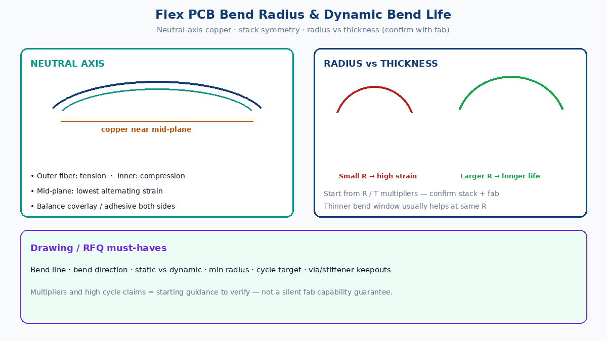
Quick answer: radius, copper position, and stack symmetry
- Place copper near the neutral axis — outer fibers stretch, inner fibers compress; the mid-plane sees the least alternating strain.
- Keep the bend stack symmetric — matched coverlay / adhesive / PI thickness on both sides of copper so the neutral axis does not drift into the foil.
- Start radius from thickness — larger R / T usually means longer life; treat published multipliers as starting guidance, then lock numbers with your fab and actual stack.
- Prefer a thinner bend window when electrical rules allow — thinner copper and thinner PI/coverlay reduce peak strain at a given radius.
- Call out bend intent on drawings — bend line, bend direction (static install vs dynamic), min radius, and cycle target (or “install only”).
- Keep stiff features out of the hinge — vias, pads, stiffeners, plated thickeners, and abrupt copper necks belong outside the flexing zone.
💡 Factory gain: Put min bend radius, static vs dynamic, target cycles, bend direction, and copper-to-neutral-axis intent on the fab drawing and RFQ. A quote that only says “flex PCB, 0.1 mm thick” is not comparable across China plants and will not protect you on field fatigue.
How stress distributes when an FPC bends
When a flex circuit bends around a radius:
| Region | Mechanical state | Risk to copper |
|---|---|---|
| Outer fiber | Tensile | Fatigue cracks, open traces |
| Inner fiber | Compressive | Buckling, wrinkling, local delam |
| Near mid-plane (neutral axis) | Lowest alternating strain | Best place for fatigue-critical conductors |
Copper is the fatigue-sensitive structure in most dynamic FPCs. If traces sit far from the neutral axis, the same radius and cycle count that “look fine” on a paper stack can crack foil early. That is why conductor position and stack symmetry matter as much as the radius number on the drawing.
Neutral-axis copper placement
For long dynamic life, design so the conductor layer sits as close as practical to the bend centerline of the finished stack (base film + adhesives + coverlays + copper). Matched thickness above and below the foil keeps that centerline where you intended.
Practical checks before RFQ:
- Single-sided dynamic window: copper between balanced coverlay/adhesive and PI, not buried under a thick one-sided build.
- Double-sided flex: if both copper layers must survive the hinge, treat each foil’s distance to the neutral axis — or thin to a single-copper bend window when possible.
- Extra adhesive or coverlay on one side only: assume the neutral axis moved; recalculate or rebalance before promising cycle life.
The closer the copper is to the neutral axis under the as-built stack (not just the CAD sketch), the better the odds of meeting the cycle target at a given radius.
Why stackup symmetry matters
A symmetrical bend stack balances tensile and compressive paths so stress does not pile onto one face of the foil. Common asymmetry traps:
| Asymmetry | What happens | Typical outcome |
|---|---|---|
| Coverlay on one side only in the hinge | Neutral axis shifts toward the covered side | Higher strain on the open-side copper |
| Thick adhesive vs thin adhesive | Centerline drifts | Early crack on the thicker-stack face |
| Stiffener edge into the bend zone | Local strain concentration | Crack at stiffener termination |
| Unbalanced copper density (solid pour vs sparse traces) | Local stiffness mismatch | Preferential cracking in denser copper |
Symmetry is a reliability control, not cosmetics. Ask CAM to flag one-sided coverlay, uneven adhesive, or stiffener encroachment in the dynamic window before you lock tooling.
Radius vs thickness — starting guidance (confirm with fab)
At the same material set, a smaller bend radius raises peak strain; a larger radius lowers it. Thicker finished flex also raises the strain difference between outer and inner fibers at a fixed radius. Industry practice often starts from a multiple of finished flex thickness T for dynamic vs static bends — for example, treating dynamic hinges more conservatively than one-time install folds.
Use those multipliers only as starting guidance:
- Confirm against your actual stack (Cu weight, PI, adhesive, coverlay).
- Confirm against the fab’s process capability and sample bend history.
- Do not treat a blog multiplier as an XFPCB (or any fab) guaranteed capability.
- Do not copy “billion-cycle” marketing numbers onto your drawing unless you own the test that produced them under your stack, radius, and motion.
Typical thickness levers that improve life at a given radius (when electrical rules allow):
| Lever | Why it helps bend life | Caveat |
|---|---|---|
| Thinner copper (e. for dynamic, often ~18 µm class vs ~35 µm) | Lower stiffness and less strain energy in foil | Ampacity / IR drop; may need wider traces |
| Thinner PI film (e.g. thinner class vs thicker class) | Smaller T → lower peak strain at same R | Tear / handling; fab capability varies |
| Thinner coverlay / adhesive | Keeps T and neutral-axis offset down | Bond strength and cover integrity |
| Single-copper bend window | Removes opposite-layer strain and thickness | Return path / EMI may need reroute outside hinge |
Always pair radius with cycle class: install/static, low-cycle service, or high-cycle continuous motion. The same R/T that passes an install fold can fail a continuous hinge.
What to put on drawings and China fab RFQs
Bend radius alone is not a complete reliability spec. Lock these on the fab drawing and RFQ package:
| Callout | Why fabs need it |
|---|---|
| Bend line / bend area outline | Defines the hinge; CAM keepouts and stiffener stops |
| Bend direction / fold sense | Which face is concave; matches coverlay and copper placement |
| Static vs dynamic | Install fold vs repeated motion — different risk class |
| Minimum bend radius | Geometry the mechanism must not undercut |
| Target cycle life (or “install only”) | Sets material / stack / test expectation |
| Finished flex thickness T in bend | Couples to R/T review |
| Copper weight + foil intent in hinge | Fatigue-sensitive; avoid silent ED/RA swaps without review |
| Via / pad / stiffener keepouts from bend line | Prevents plated and stiff features in the hinge |
| Test method / acceptance (if any) | Continuity under bend, cycle count, failure criteria |
Attach a short mechanical sketch showing the bend line, radius, and motion path. Vague “flex, good bend life” language produces non-comparable China quotes and late NPI surprises.
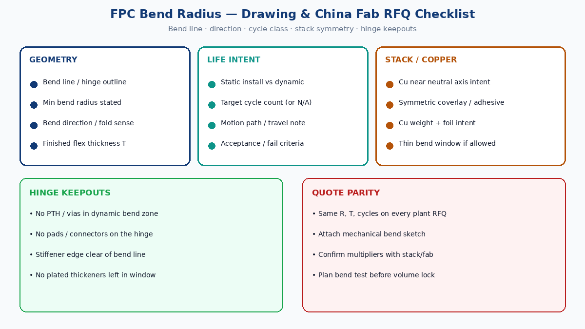
Keep thick and plated features out of the hinge
Features that raise local stiffness or introduce brittle copper should sit outside the dynamic bend area:
- Plated through vias and via fill in the hinge
- Component pads and connectors on the flexing zone
- Stiffeners that terminate inside the bend radius
- Abrupt neck-downs and solid copper pours that create strain concentrators
- Electroplated thickeners left on in the bend window
Route critical nets through the hinge with smooth, adequately wide traces; place vias and pads on rigid or stiffened regions when the product allows. Geometry keepouts and via fatigue details belong in companion DFM notes — here the rule is simple: hinge = thin, symmetric, copper near center, clean of stiff islands.
Verify with bend testing, not theory alone
Stack equations and radius multipliers are planning tools. Dynamic life should be confirmed on the as-built construction under a defined radius, travel, frequency, and failure criterion. Industry flex endurance methods (for example dynamic bend models referenced in common test collections such as IPC-TM-650 style flex fatigue setups) give a shared language for sample size, radius, and continuity monitoring.
Define early with your fab or test house:
- Test bend radius and motion envelope
- Bending frequency and travel
- Target cycle count and pass/fail (open, resistance rise, visual crack)
- Whether real-time continuity monitoring is required
- How sample stack matches production (foil, PI, coverlay, adhesive)
NPI that skips bend testing and only checks first-article continuity after a hand fold is not a dynamic-life qualification.
Practical design checklist for dynamic FPC bend life
| Check | Pass criteria |
|---|---|
| Copper vs neutral axis | Foil near mid-plane of finished bend stack |
| Stack symmetry | Coverlay / adhesive / PI balanced on both sides of Cu |
| Radius vs thickness | R sized for dynamic class; multiplier confirmed with fab |
| Bend window thickness | As thin as electrical and handling allow |
| Drawing callouts | Bend line, direction, static/dynamic, min R, cycle target |
| Keepouts | No vias, pads, stiffeners, or plate thickeners in hinge |
| RFQ parity | Same stack, foil intent, R, and cycles on every plant quote |
| Test plan | Defined radius, cycles, and continuity fail criteria before volume |
Closing
Pure FPC dynamic reliability is a stress-control problem: put copper near the neutral axis, keep the bend stack symmetric and thin, size bend radius against finished thickness and cycle class, and write bend line / direction / cycle target on the drawing so China fabs quote the same intent. Treat radius multipliers and high cycle-count claims as guidance to verify — not as a silent guarantee. Lock the RFQ, then prove the stack with bend testing before volume.