
Board-level EMI shield cans and conductive coatings on plastic housings are the two methods buyers most often argue after fundamentals are settled. A soldered can isolates a noisy island on the PCB; a conductive paint turns a plastic shell into a crude Faraday skin. Neither replaces continuous reference planes or stitch discipline — and China PCBA lines will invent pick-up, paste, and land defaults if the RFQ is silent. This is the methods deep dive: can materials and SMT DFM, fixed vs removable, design factors (height, power, frequency, gaps, BeCu springs), coating process traps, and a can-vs-coating-vs-both decision matrix.
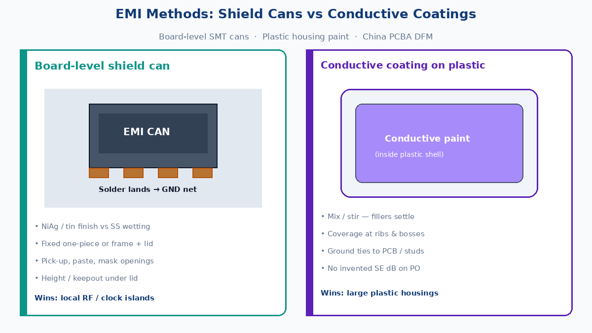
Answer first: can, coating, or both
| Question | Factory / procurement answer |
|---|---|
| Why shield at board / enclosure? | Contain an aggressor island or harden a plastic shell so energy does not leak / enter — methods after planes and zoning exist |
| What is a shield can? | Drawn / stamped metal cover soldered (or clipped) to PCB ground lands — SMT or hand place |
| Fixed vs removable? | Fixed = one-piece soldered lid (cheapest, hard to rework). Removable = soldered frame + snap / spring lid (debug / rework access) |
| Where cans win | Discrete RF / clock / converter islands; defined keepout; need hard local attenuation on the board |
| Where coatings win | Large plastic housings; no room for a can; whole-product skin; cost-sensitive consumer shells |
| When both? | Noisy PCB islands under cans plus painted / coated enclosure for system-level containment |
| Fear list (implicit) | Can on wrong net; SS can that will not wet; settled paint with thin spots; lid gaps that radiate |
💡 Procurement tip: Put can footprint / height / material / finish (NiAg vs SS), fixed vs removable frame, land net + mask openings, and coating coverage + mix/stir notes on the RFQ. “EMI shield” with no method is how quotes mix a can line and a spray line without matching the design.
Why you still need a method after fundamentals
Planes, stitch fences, and zone maps decide whether a barrier has a return. Methods decide where metal sits:
- Board-level can — short Faraday box over one IC or block, tied to the board ground net through solder lands.
- Enclosure coating — conductive film on the inside of a plastic housing, tied to chassis / PCB ground at defined contact points.
- Both — common when the board has hot islands and the product shell is plastic with no metal die-cast body.
Skipping the method choice and ordering “add EMI” after layout freeze is how pre-scan fails twice: once for the island, once for the shell aperture.
Shield can — definition, materials, SMT
A shield can (EMI can / RF can / fence-and-lid) is a thin metal enclosure that sits on the PCB and covers a keepout zone. Production forms:
| Form | How it attaches | Factory note |
|---|---|---|
| One-piece soldered can | Entire drawn box reflowed to perimeter lands | Fast SMT; lid is permanent |
| Two-piece (frame + lid) | Frame soldered; lid snaps or springs on | Removable for debug / rework |
| Fence / wall only | Perimeter wall without full lid | Partial; often pairs with a lid later |
Materials buyers actually quote
| Material / finish | Why it shows up | SMT / solderability |
|---|---|---|
| Tin-plated steel or nickel-silver (NiAg) class | Common SMT cans; solderable skirts | Good wetting on paste lands when finish is specified |
| Stainless steel (SS) | Stiffness / corrosion stories | Often poor solder wetting unless plated or process-qualified — call finish explicitly |
| Aluminum | Light, conductive | Usually not a drop-in solder can without special attach |
| Copper / brass family | High conductivity | Cost / oxidation / finish must be on the traveler |
Factory rule: Do not assume “metal can = solderable.” NiAg / tin-finish cans and SS cans are different paste and heat stories. Put material + surface finish on the BOM and assembly notes.
SMT pick-up and land pattern (China PCBA DFM)
What the SMT line needs called out:
| DFM item | Why |
|---|---|
| Pick-up surface | Flat lid top for nozzle; tape/reel or tray packaging; no warped drawn parts that fail vision |
| Land pattern | Continuous or segmented ground pads matching the can skirt; clearance from signals under the wall |
| Mask openings | Solderable pads — masked “ground” under the skirt does not wet |
| Paste aperture | Enough paste for fillet without bridging into the keepout or adjacent pads |
| Height / keepout | Can clearance above tallest part under the lid; nozzle and neighboring tall parts |
| Polarity / orientation | Asymmetric cans need silkscreen or feeder notes |
A can that looks fine in 3D and fails first article because the skirt sits on soldermask or the nozzle cannot grip a glossy lid is a drawing failure, not a mystery EMI fail.
Fixed vs removable — debug and rework decision
| Type | Structure | Wins when | Loses when |
|---|---|---|---|
| Fixed (one-piece) | Whole can soldered | Cost, cycle time, no lid logistics | Must desolder to probe / replace the IC under the can |
| Removable (frame + lid) | Soldered frame; snap or spring lid | Bring-up, field rework, FA access, iterative EMC tweaks | Extra part, lid retention QC, spring contact quality |
Procurement framing:
- Prototype / NPI / RF modules that will be probed → budget removable.
- Locked consumer BOM with no under-can service → fixed is fine.
- Mixed: solder a frame early, ship lids after EMC tune — only if the traveler allows staged assembly.
Removable is not “more EMI.” A loose lid with daylight at the seam can radiate worse than a well-soldered fixed can. Retention and seam continuity are part of the EMI design, not packaging cosmetics.
Design factors that decide can performance
Textbook “metal box” fails in production for mundane geometric reasons:
| Factor | What goes wrong | Buyer / layout lever |
|---|---|---|
| Height | Parts touch the lid (shorts / abrasion) or too-tall can fights the enclosure | Max part height + clearance note; can height on RFQ |
| Power / heat | Can traps heat on a hot regulator or PA | Thermal vias, vent slots (slots are apertures — trade carefully), or leave the thermal island un-canned |
| Frequency | Slot / gap length approaches wavelengths of concern | Keep seams short; stitch density under the skirt; no long ungrounded slots “for airflow” without EMC review |
| Gaps / seams | Lid-to-frame gap, cutouts for connectors, incomplete solder | Spec max gap intent; BeCu or spring fingers where lids remount |
| BeCu springs / fingers | Removable lids need reliable ground at the seam | Call spring material / plating; inspect crush set and plating wear on rework cycles |
Gaps dominate. A beautiful can with a 10 mm ungasketed connector cutout is an intentional aperture. Treat every opening as an EMC feature on the drawing.
Where cans win
Cans are the right first method when:
- The aggressor (or victim) is a compact board island with a clear keepout.
- You need local containment without painting the whole product.
- SMT capacity and land nets already exist on the board.
- Removable access to one RF / clock block matters more than enclosure paint QA.
- The housing is already metal — coating adds little; the residual problem is on-PCB.
Cans lose when the shell is large plastic with many seams, the noise is system-level cable/aperture driven, or there is no space for a can footprint and height.
Conductive coating / paint on plastic housings
Conductive coating (nickel, copper, silver-filled paints and similar production coats — quote by generic chemistry class, not brochure brand) is sprayed or otherwise applied to the inside of plastic enclosures so the shell behaves more like a conductive barrier. Typical jobs:
- Consumer / IoT plastics that cannot afford die-cast metal
- Large volumes where a can cannot cover every aggressor
- Closing the system Faraday story when the PCB already has local cans — or when cans are impractical
What the coat must do electrically
| Need | Factory language |
|---|---|
| Continuous coverage | No thin spots at corners, ribs, or boss shadows |
| Ground tie | Defined contact to PCB ground / chassis studs / EMI gaskets — floating paint is a floating hope |
| Adhesion | Paint that peels after drop / humidity is an open seam |
| Thickness class | Call the process window the coater qualifies — do not invent dB claims on the PO |
Process traps — mixing, settling, coverage (qualitative)
Filled conductive paints settle. Pigment and binder separate in the can and in the spray pot.
| Trap | What happens | Control |
|---|---|---|
| No stir / incomplete mix | First parts rich, later parts starved — or the reverse | Timed mix / stir before and during spray; pot agitation per process sheet |
| Settling in hose / gun | Patchy conductivity; “looks coated” visually | Recirculation / purge discipline; first-article conductivity check |
| Shadowing | Ribs, bosses, deep draws miss paint | Spray angles, multiple passes, mask strategy |
| Over-thin / over-thick | Thin = weak barrier; thick = peel, orange peel, fit issues | Qualified wet-film / process coupon — not eyeball |
| Ground contacts painted shut or left bare wrong | Opens or shorts at studs / spring contacts | Mask map on the coating drawing |
Failure path: paint looks uniform in photos → settled batch ships thin at corners → pre-scan fails → team adds a can on the PCB → second fail because the shell aperture still dominates. Coat process QA is EMI QA.
Can vs coating vs both — decision matrix
| Situation | Prefer | Why |
|---|---|---|
| One noisy IC / RF block on a dense board | Can | Local, SMT-friendly, clear keepout |
| Need probe / rework under the shield | Removable can | Frame + lid; springs if specified |
| Large plastic consumer shell, few board islands | Coating | System skin without many can footprints |
| Hot PA + plastic IoT box + cable exits | Both + aperture discipline | Can on PA; coat shell; gasket / cable entries still required |
| Metal enclosure already continuous | Can (board) or nothing extra | Coating on metal is usually wasted |
| No land net, no height, layout frozen | Coating or enclosure gasket path — not a late can fantasy | Late cans on wrong nets still fail |
Both is not “belt and suspenders free.” It is two travelers: SMT can DFM and coating mix/coverage/ground-tie notes. Quote both lines or accept that one will be guessed.
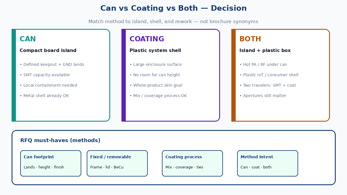
China PCBA / SMT DFM checklist for cans
Hand this to the assembly house with the BOM:
- Footprint — land pattern, segment vs continuous skirt, clearances.
- Height — can ID height vs max component under lid + clearance.
- Material + finish — NiAg / tin-plate vs SS (and plating if SS).
- Fixed vs removable — one-piece or frame+lid; lid retention method.
- Pick-up — packaging, top flatness, polarity.
- Paste / mask — openings on can lands only; paste volume note if non-standard.
- Net — can lands on the intended ground; no signal under the wall.
- Keepouts — no vias/solder beads that lift the skirt; no tall neighbors in the nozzle path.
- BeCu / springs — if removable, spring count, plating, and inspection after rework.
- AOI / FA — solder fillet criteria for the skirt; lid seated check for two-piece.
Coating RFQ fields (when the shell is in scope)
If XFPCB or a partner quotes PCBA and you own the plastic coat:
- Chemistry class (Ni / Cu / Ag-filled — generic) and qualified applicator
- Coverage map (faces, ribs, exclusions)
- Mix / stir / pot-life notes on the process sheet
- Ground-tie locations to PCB / studs
- First-article conductivity or continuity method (qualitative acceptance — no invented SE numbers)
- Mask-offs for bearings, optics, logos, mating surfaces
Buyer RFQ checklist (methods → factory)
- Method intent: can / coating / both — not “EMI TBD.”
- Can: footprint, height, material, finish, fixed vs removable.
- Can lands: net, mask openings, paste, pick-up, keepout.
- Removable: frame + lid + spring/BeCu notes if used.
- Coating: coverage map, mix/stir discipline, ground ties.
- Apertures: connector / display / cable exits called as EMC features.
- Do not invent shielding-effectiveness dB limits on the PO — attach the test plan or customer annex.
- Align with plane / stitch fundamentals already on the fab notes; a can on a broken return still fails.
What this post is — and what it is not
| Covered here | Covered elsewhere |
|---|---|
| Board-level cans: materials, SMT DFM, fixed vs removable | EMC/EMI/EMS vocabulary, reflection/absorption physics |
| Design factors: height, heat, frequency, gaps, BeCu | Flex silver-paste / carbon / foil constructions |
| Conductive coatings on plastic + mix/settle traps | Quantitative SE tables and legal limit values |
| Can vs coating vs both matrix + RFQ fields | Cable braid / gasket encyclopedia |
This slug is the methods companion to fundamentals and flex constructions: rigid-board cans, enclosure coatings, and the China PCBA notes that make either buildable.
Shield cans and conductive paints are tools. Continuous returns, honest land nets, and stirred paint are how the method you paid for is the method that ships.