
EMI shielding is the use of conductive or magnetic barriers to keep unwanted electromagnetic energy out of a protected volume — or keep energy generated inside from leaking out. EMC (electromagnetic compatibility) is the broader goal: the product neither pollutes its neighbors nor fails when neighbors pollute it. Buyers who treat shielding as a last-minute can or coating, after the stackup and return paths are frozen, often discover the problem in CE/FCC pre-scan — and pay for enclosure add-ons that a continuous plane and a few stitch notes would have reduced.
Answer first: definitions, how it works, buyer levers
| Question | Factory / procurement answer |
|---|---|
| What is EMI shielding? | Conductive / magnetic barrier that attenuates interference by reflection, absorption, and partial cancellation |
| EMI vs EMC? | EMI = the unwanted energy / disturbance. EMC = the design goal to emit less and survive more |
| What is EMS? | Electromagnetic susceptibility — how easily the product is disturbed (immunity’s opposite face) |
| How does a shield work? | Impedance discontinuity reflects; material loss absorbs; induced opposing fields cancel part of the residual |
| HF vs LF material? | HF → low-resistivity conductors. LF magnetic → high-permeability materials. Broadband → often multilayer |
| Active vs passive? | Passive = keep outside noise out. Active = contain an inside source (classically low-frequency use) |
| What belongs on fab notes / RFQ? | Planes / return continuity, stitch / via fence intent, shield-can land nets, finish & keepouts — before late can retrofit |
| Fear list (implicit) | CE fail late; shield bolted on after layout freeze; broken return path under a “shielded” zone |
💡 Procurement tip: Put EMC intent + shield-can land net + stitch/fence note + plane continuity on the fab notes / RFQ. “Add shielding later” with no stackup or ground rule is how quotes ignore EMC and pre-compliance fails after tooling.
EMC, EMI, EMS — three labels, one problem set
| Term | Plain meaning | Buyer use |
|---|---|---|
| EMC | Product works in its EM environment and does not make that environment worse for others | Market gate (CE / FCC-class paths, customer EMC specs) |
| EMI | Unwanted EM energy that couples and disrupts | Root cause language in FA / lab reports |
| EMS | How sensitive the product is to external disturbance | Immunity / anti-interference side of EMC |
EMC is not “pass radiated emissions only.” Emissions and immunity both matter. A board that is quiet in a chamber but resets when a radio key-fob clicks nearby still failed the coexistence job.
EMI vs EMC in one line
EMI is the interference. EMC is controlling that interference so the product stays reliable. Shielding is one control method among stackup, filtering, layout, and enclosure — not a synonym for EMC.
Everyday picture: “snow” on a TV
Older analog TV “snow” is a useful mental model: the wanted signal is present, but noise energy rides in and the picture breaks up. Same physics class shows up as:
- Audio hash on a poorly referenced ADC
- Packet errors next to a switching regulator
- A module that works on the bench and fails next to a motor drive
Shielding does not invent a perfect signal — it reduces how much of that snow can enter (or leave) the volume you care about.
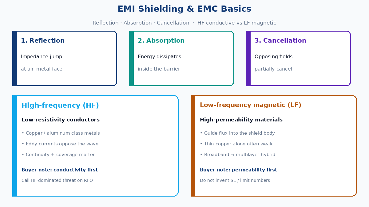
Why shielding reduces interference — three effects
Shielding effectiveness is not one trick. Practical barriers combine:
| Effect | What happens | Design note |
|---|---|---|
| Absorption | Wave energy dissipates in the material (eddy-current / loss mechanisms) | Thickness and material loss matter more as frequency and skin behavior change |
| Reflection | Impedance jump at air–metal (or coating) interface sends energy back | Interface effect — reflection does not require “infinite thickness” |
| Cancellation | Induced currents / opposing fields partially cancel the incident field | Works with continuous conductive paths; seams and slots undermine it |
Residual energy that still crosses the first surface can hit the far interface and bounce again (multiple reflections), adding more attenuation in some structures. Factory language: a shield is only as good as its continuous conductive path to the reference you intended — a floating foil with no ground strategy is a floating hope.
Frequency decides materials (qualitative)
Do not treat one metal as universal. Frequency class drives the qualitative choice:
High-frequency interference → conductive (low resistivity)
At higher frequencies, low-resistivity metals (copper, aluminum, and similar conductors in production use) are the usual first pick. HF fields induce eddy currents readily; conductivity and continuous coverage dominate the conversation more than bulk magnetic permeability.
Low-frequency magnetic interference → high-permeability materials
At low frequencies, ordinary thin conductors often under-perform against magnetic fields. High-permeability materials guide flux into the shield body and away from the protected volume. Here permeability matters more than “just add copper.”
Need both bands → multilayer / hybrid stacks
When the threat spans HF and LF, single-material shields often disappoint. Engineering practice uses multilayer stacks (conductive + magnetic layers, or dissimilar metals) so each layer works where it is strong. On a PCB RFQ this shows up as enclosure material notes or board-level foil/can specs — not as a free “EMI coating” checkbox with no frequency intent.
Factory rule: State the threat class (HF-dominated / LF magnetic / broadband) on the RFQ when shielding materials are part of the buy. Silent “EMI shield required” invites the cheapest conductor film that fails the real spectrum.
How attenuation builds at the barrier
From the wave’s point of view:
- Surface reflection — first impedance discontinuity rejects part of the energy.
- Internal absorption — energy that enters the material decays while traveling.
- Far-side / multiple reflections — leftover energy meets another interface and can bounce back into lossy material again.
That is why seams, cable exits, display openings, and connector cutouts dominate real products: they create intentional or accidental apertures that bypass the textbook wall. Methods for cans, gaskets, and cable shields belong in a methods deep-dive — this fundamentals post stops at the physics and the PCB / buyer notes that decide whether those methods have a chance.
Why EMC standards matter (market gate, not a number dump)
National and industry EMC frameworks typically constrain:
- How much the product may radiate and conduct onto lines
- How much disturbance the product must tolerate (immunity)
Different product categories (consumer, industrial, medical, telecom) map to different standard families and test setups. Exact limit values belong in the applicable standard and test plan — this article does not invent dBµV/m numbers.
For procurement:
| Gate | What it means commercially |
|---|---|
| Pre-compliance scan early | Catches plane / return / clock-edge disasters before enclosure tooling |
| Formal compliance path | Market access for many regions and OEM contracts |
| Customer EMC annex | Often stricter or differently scoped than the legal minimum |
Passing functional QA while failing EMC is still a failed shipment for many buyers. Treat standards as a market gate, not optional polish.
Active vs passive shielding — enclosure vs PCB can decision
By where the source sits relative to the barrier:
| Type | Source location | Job | Typical use framing |
|---|---|---|---|
| Passive shielding | Outside the shield | Keep external fields out of a quiet volume | Shielded rooms, quiet zones, sensitive front-ends |
| Active shielding | Inside the shield | Keep internally generated fields from leaking out | Noisy converters, clocks, RF blocks contained in a can / enclosure |
Decision for enclosure vs PCB can (buyer-level):
- Contain a noisy island on the board → PCB-level can / fence + solid reference (active-style containment for that island).
- Protect a quiet product from a harsh plant floor → enclosure / room-level passive shielding, plus cable entry discipline.
- Both → common in mixed products: board cans on aggressors and a conductive enclosure for the system.
Classical active-shielding discussion is strongest at low frequency; do not assume the same structure is a free HF fix. Frequency still owns material and aperture rules.
PCB-level EMC basics buyers put on fab notes
This is the factory gain of this fundamentals post — not a methods catalog for cans, gaskets, or cable braids (those wait for the methods article). What CAM and SMT actually need called out:
| Fab-note / RFQ item | Why it exists | Failure if omitted |
|---|---|---|
| Continuous reference planes under aggressors / victims | Return current has a short path; loop area drops | Return snakes through slots → radiation and susceptibility |
| Return-path / plane split rules | Splits under high-speed or noisy nets create antennas | “Shield” lands on a broken reference still fails scan |
| Via stitch / fence intent (qualitative: around can, along zone) | Ties copper lids / fences to the intended ground | Floating stitch rings; can lands on wrong net |
| Shield-can land nets + keepouts | SMT can solder to defined pads; height/keepout for pick-place | Can lands on signal; paste shorts; no ground |
| Finish / mask openings on can lands | Solderable land definition | Masked pads → tombstone / no bond |
| Zone map (noisy / quiet / RF) | Guides placement and which islands need containment | Blanket “EMI coating” with no zoning |
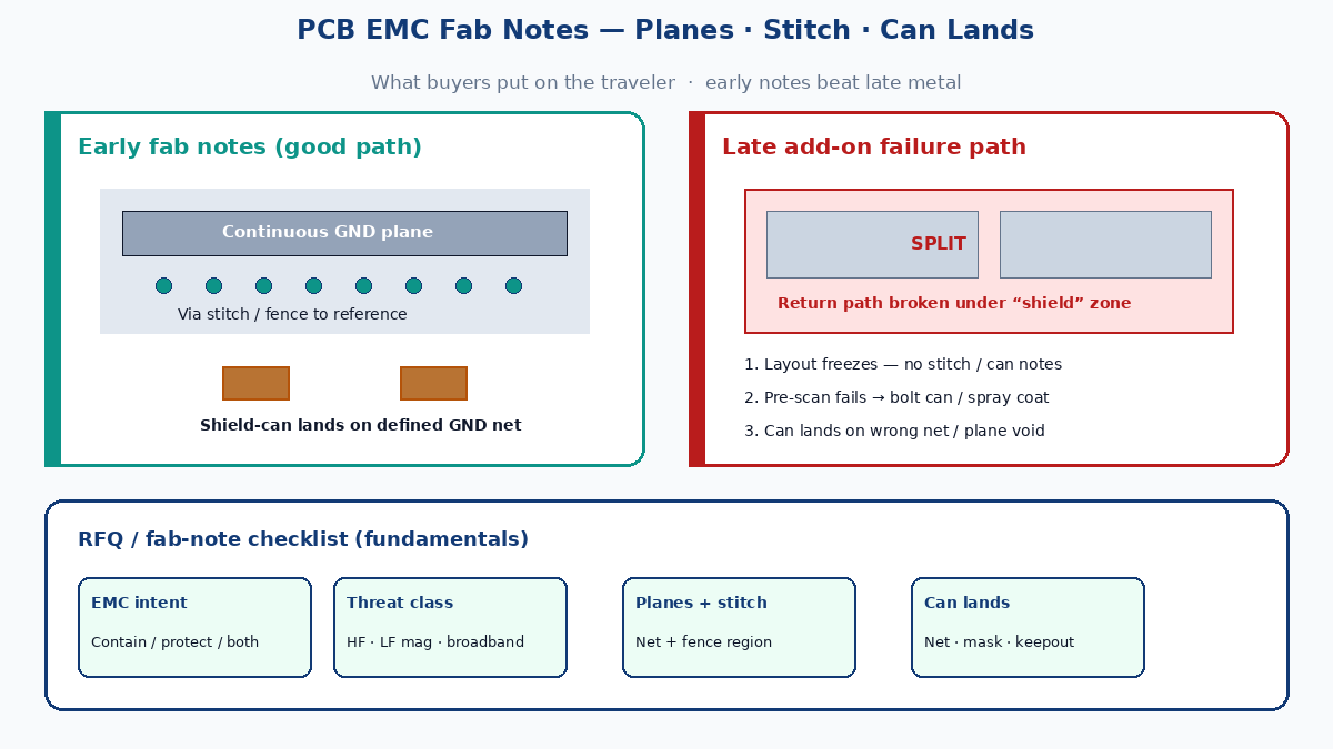
Late shield add-on failure path
Layout freezes without plane / stitch notes → pre-scan fails → team bolts a can or spray coat → can lands sit on mixed nets or over plane voids → second scan still marginal → schedule burns while the fab re-quotes mask and paste. Early fab notes beat late metal.
What this post is — and what it is not
| Covered here | Left for methods / flex deep-dives |
|---|---|
| EMC / EMI / EMS vocabulary | Detailed can / gasket / cable braid procedures |
| Reflection / absorption / cancellation | Quantitative SE tables and invented limit values |
| HF conductive vs LF magnetic (qualitative) | Flex silver-paste / carbon / foil process recipes |
| Active vs passive decision framing | Full enclosure aperture engineering |
| PCB fab notes: planes, stitch, can lands | Step-by-step retrofit cookbooks |
Existing XFPCB flex EMI content focuses on flex constructions and paste/foil stacks. This slug is the rigid/system fundamentals + buyer RFQ companion: definitions, physics, standards-as-gate, and what to print on fab notes before anyone orders a can.
Buyer RFQ checklist (fundamentals → factory)
- State EMC intent (contain aggressor / protect victim / both) and threat class (HF / LF magnetic / broadband).
- Call plane continuity and forbidden splits under critical nets.
- Note stitch / via fence regions and the ground net they must hit.
- Define shield-can land nets, mask openings, and mechanical keepouts if a can is planned.
- Name the compliance path (standard family / customer annex) without pasting fake limit numbers — attach the test plan when you have one.
- Do not rely on “add EMI later” as the only plan; late barriers on broken returns still fail.
Shielding is a tool. EMC is the goal. Continuous returns and honest fab notes are how China fab and your compliance lab stay on the same traveler.