
A flex PCB stiffener is not a decorative FR4 patch. It is a local rigidity island you add so a connector can insert, an SMT land can reflow without trampoline warp, a leaded or through-hole part can survive soldering and handling, or a metal plate can sink heat / add EMI mass. Get material, adhesive, side, and edge keep-out wrong and you create a new crack path at the stiffener edge — often blamed on “bad flex” when the drawing never locked the application.
This playbook is an application selection map: use-case → material and adhesive → stiffener side and edge keep-out → drawing and RFQ. It is not a ZIF / FFC connector-tail finished-thickness DFM rewrite (that live playbook is the connector-tail article). It is not bend-failure diagnosis. Thickness bands below are industry starting guidance only — confirm every mm with your fab and stack.
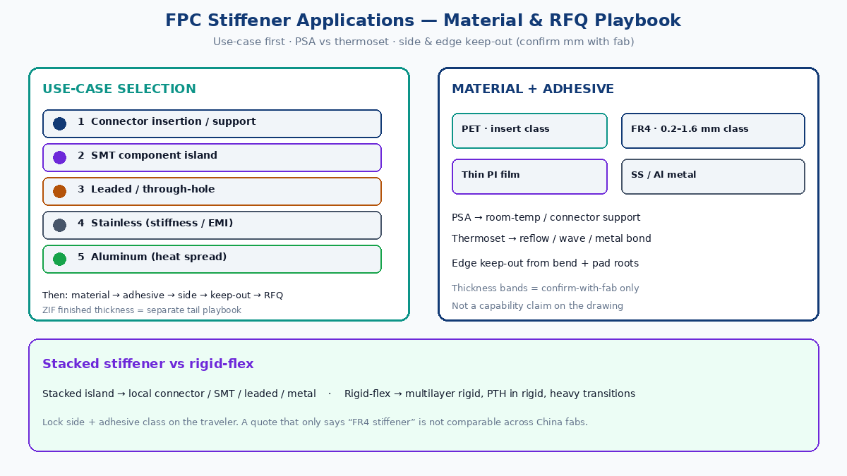
Quick answer
- Name the use-case first — connector insertion / support, SMT component island, leaded or through-hole soldering, or metal duty (thin stainless for high stiffness / EMI mass; aluminum when heat spread matters). Do not RFQ “add stiffener” with no duty.
- Pick material for the duty — PET film for thin insert-zone reinforcement; FR4 for most SMT and leaded islands; thin polyimide film when you need a light stiffener without FR4 thickness; stainless or aluminum only when metal’s stiffness, EMI, or thermal job is real.
- Choose adhesive by process — PSA (pressure-sensitive) for many connector and room-temp attach jobs; thermoset / heat-bond when reflow, wave, or higher peel at temperature is required. Do not mix adhesive families on one traveler without calling them out.
- Lock stiffener side and edge keep-outs — which face gets the stiffener relative to pads / components; edge distance from dynamic bend and from solder joints / pad roots. Edge location kills more assemblies than material brand.
- Decide stacked stiffener vs rigid-flex — stacked stiffener wins for local islands and cost; true rigid-flex wins when you need multilayer rigid circuitry, plated through in the rigid, or many transitions that stacked islands cannot manage cleanly.
- Issue RFQ with outline, stack, side, adhesive, keep-outs, and confirm-with-fab thickness — same package to every plant so quotes are comparable.
Factory tip: A quote that only says “FR4 stiffener” without use-case, side, adhesive class, outline, and edge keep-out from bend is not a stiffener quote — it is a guess. Plants will default to shop habit and your first articles will teach you what they assumed.
Why stiffeners exist on FPC (and what they are not)
Bare polyimide flex is meant to bend. Connectors, chip packages, and leaded parts are not. A stiffener restores a local rigid zone so:
- Insertion force does not buckle a soft tail.
- Reflow does not warp a thin land into opens or tombstones.
- Hand or wave solder on a leaded part has a stable work surface.
- Screws, shields, or heat paths have something to land on besides film.
A stiffener is not a bend-radius substitute, not multilayer rigid (that is rigid-flex), and not automatic EMI cover unless metal is bonded for that duty. Spec outline, thickness, adhesive, and side on the fab drawing.
Use-case selection tree
| Use-case | What the stiffener must do | Material leaning | Adhesive leaning | Side / edge note |
|---|---|---|---|---|
| Connector insertion / support | Hold finished thickness and resist buckle on mate | PET (thin insert class) or FR4 / PI film per connector duty | Often PSA for PET insert; thermoset when heat or higher peel needed | Stiffener usually opposite contact pads; edge keep-out from pad root and from form bend — finished insert thickness details live in the ZIF/FFC tail playbook |
| SMT component island | Flat, stable land for reflow of QFN / BGA / discretes | FR4 common; thin PI when height budget is tight | Thermoset preferred under reflow; confirm PSA grade if used | Stiffener typically opposite components; keep edge away from dynamic bend and from fine-pitch pad edges |
| Leaded / through-hole | Stable soldering and pin support; survive hand/wave | FR4 (thicker class often) | Thermoset for solder heat; avoid soft PSA under pin stress | Side per pin access; edge keep-out from solder joints and from flex hinge |
| Thin high stiffness / EMI mass | High modulus in small thickness; optional shield mass | Stainless steel (thin gauge) | Bond adhesive rated for metal + flex CTE; often thermoset | Watch galvanic / finish; edge keep-out still required — metal edge is a sharper crack starter |
| Heat spread / thermal island | Move heat off a hot part or LED | Aluminum | Thermally aware adhesive; confirm with fab | Side toward heat source path; do not place Al edge in dynamic bend |
Start from the left column. If the RFQ only lists “0.3 mm stiffener” with no use-case, plants will quote PET, FR4, or PI interchangeably and you cannot compare cost, peel, or crack risk.
ZIF / FFC boundary: Connector-tail finished reinforced thickness, contact side, pad geometry, and insert-zone DFM belong in the live ZIF/FFC connector-tail playbook. This article only maps when a connector-support stiffener is the right application vs SMT / leaded / metal options — and how to choose material and adhesive for that map. Do not merge both RFQ note sets into one vague “stiffener” line.
Material map (confirm thickness with fab)
| Material | Typical job | Industry thickness band (starting guidance) | Watch-outs |
|---|---|---|---|
| PET film | Thin connector insert-zone reinforcement | Insert-zone finished stack often discussed in a ~0.3 mm class (flex + adhesive + PET) — confirm with connector datasheet and fab | Soften / creep at elevated temp; wrong for heavy reflow islands |
| FR4 | SMT islands, leaded/TH support, general local rigidity | 0.2–1.6 mm class common in buyer discussions — pick by height budget and solder process; confirm with fab | Thick FR4 at a bend edge is a classic crack starter; routing FR4 outline matters |
| Thin polyimide (PI) film | Light stiffener when FR4 is too thick or PET too soft | Thin-film class (tens to low hundreds of µm) — confirm with fab | Not a substitute for multilayer rigid; peel and registration still need notes |
| Stainless steel | Thin high stiffness; EMI / mass when designed in | Thin gauge sheets — confirm gauge and bond process with fab | Sharp modulus step; finish / corrosion; harder laser/route than FR4 |
| Aluminum | Heat spread under power / LED / hot ICs | Gauge by thermal need — confirm with fab | CTE vs PI; electrical isolation if Al must not short; edge keep-out |
Do not treat any band above as an XFPCB capability number — confirm with fab stack-up review. A thin PET/FR4/PI table without adhesive, side, and keep-out is how stiffener respins start.
PSA vs thermoset adhesive
Adhesive is a process decision, not a brand preference.
Prefer PSA when:
- Attach is room-temperature or low-heat and peel duty is moderate.
- Many connector PET stiffeners and some non-reflow support islands.
- You need reworkable or process-simple bonding the fab actually runs for that material.
Prefer thermoset (heat-bond / epoxy class) when:
- The island sees reflow, wave, or sustained high temperature.
- Peel strength at temperature must hold under component or lead stress.
- Metal stiffeners (stainless / aluminum) need a bond that survives thermal and mechanical load.
Decision checks for the RFQ:
- Max process temperature after stiffener attach (reflow profile? hand solder?).
- Peel / shear duty (insertion only vs component weight vs screw clamp).
- Whether the fab bonds stiffener before or after coverlay / finish (sequence changes allowable adhesive).
- Outgassing or ionic limits if the product is sealed or high-reliability — ask; do not invent a spec from a blog.
A plant that quotes “FR4 stiffener, adhesive TBD” is asking you to accept their default. Name PSA vs thermoset class (or the fab’s equivalent process family) on the drawing note.
Stiffener side rules
Side errors look like fab defects on the line and are usually design omissions.
- Connector support: stiffener is commonly on the face opposite the contact pads so the wipe face stays clear and thickness builds on the back. Confirm against the connector drawing — some housings flip the habit.
- SMT island: stiffener usually opposite the component side so the land stays flat and accessible to paste and nozzles. Dual-side SMT on a stiffened zone needs an explicit stack conversation (often rigid-flex territory).
- Leaded / TH: choose the side that leaves pin access and soldering clear; do not bury the work face under FR4.
- Metal: place for the mechanical / thermal / EMI intent; isolate electrically if the plate must not short nets or ESD paths.
Put stiffener side on the same drawing note as material and thickness. Shop-default side is a frequent full-lot miss on fast-turn FPC.
Edge keep-out: bend and solder joints
The stiffener edge is a stiffness step. Copper and coverlay see elevated strain there during bend, insertion, and thermal cycle.
From dynamic bend / hinge:
- Keep the stiffener outline out of the designed bend region.
- Leave a keep-out between stiffener end and the start of the bend radius — enough that the flex can form without a sharp modulus cliff at the copper.
- Vias, abrupt coverlay steps, and component pads jammed against the stiffener edge compound the crack risk.
From solder joints and pad roots:
- Do not end FR4 or metal directly under or at the root of fine-pitch pads you still expect to flex slightly.
- For connector tails, stiffener edge vs pad root is a known tear starter — detail belongs in the connector-tail thickness playbook; here: mark edge keep-out on every stiffened application, not only ZIF.
- For SMT, keep the stiffener edge outside the paste/land cluster so the island perimeter does not become a tombstone driver.
Keep-out distances vary with thickness, material, and bend duty — confirm with fab and reliability. Do not freeze a blog millimetre as a capability claim.
When rigid-flex beats a stacked stiffener
Stacked stiffener (flex + bonded FR4/PET/PI/metal) is the right first tool for local islands. Switch the conversation to rigid-flex when:
- You need multilayer rigid circuitry, planes, or impedance control in the rigid section — not just a dumb spacer.
- You need plated through-holes that belong to the rigid stack, not pins forced through a bonded FR4 island with weak annular control.
- Transition count, bookbinder folds, or reliability duty make many bonded islands harder to control than a designed rigid-flex stack.
- Height, registration, and adhesive peel of stacked islands already fail FAI or field tear-downs.
Rigid-flex has its own DFM and bend-failure playbooks. Do not treat thicker FR4 as a silent upgrade into multilayer rigid — ask which construction the fab will run and price.
Drawing notes that prevent stiffener respins
Put on the fab drawing (or a controlled process sheet the drawing references):
- Use-case class (connector support / SMT / leaded-TH / metal thermal / metal EMI-stiffness).
- Material and nominal thickness (with “confirm stack with fab”).
- Adhesive class: PSA vs thermoset (or named fab process).
- Stiffener side relative to pads / components / connector contacts.
- Outline (DXF / Gerber mechanical) and tolerance class.
- Edge keep-outs from bend region and from critical pad roots / solder joints.
- Sequence note if stiffener bonds before or after finish / coverlay matters.
- FAI: measured thickness in the stiffened zone (where relevant), peel sample if required, and photo of edge registration.
For connector insert zones, send thickness and contact-side details to the connector datasheet and ZIF/FFC tail notes — avoid conflicting mm targets on two balloons.
Buyer RFQ checklist
Ask every China fab the same package so quotes line up:
- Confirm use-case class and recommended material family (PET / FR4 / PI / stainless / aluminum).
- Confirm adhesive class (PSA vs thermoset) for your max process temperature.
- Confirm stiffener side and outline they will CAM from your mechanical layer.
- Confirm edge keep-out practice from bend and from pad roots for your thickness class.
- Confirm whether stacked stiffener is enough or they recommend rigid-flex for your transition / via needs.
- Confirm measured FAI thickness method in the stiffened zone (especially connector support) — datasheet target vs plant capability.
- Same questions to every plant; reject quotes that only say “standard stiffener.”
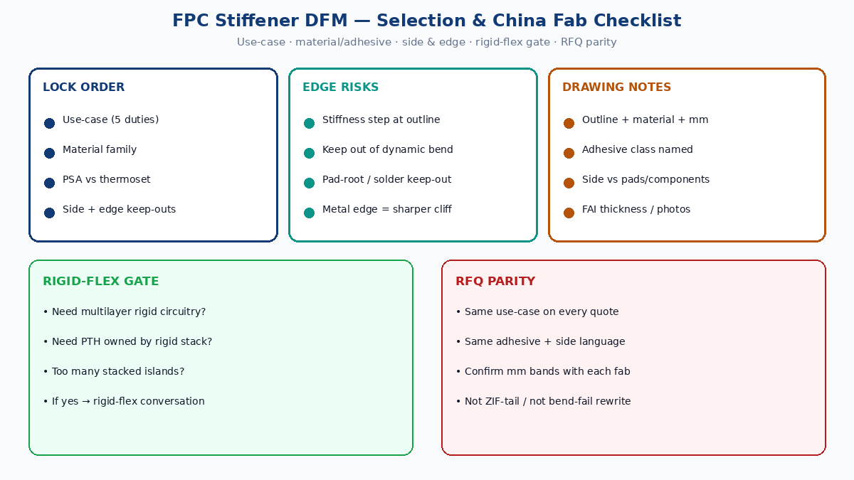
Lock use-case before material, adhesive before traveler habit, and edge keep-out before a cheap FR4 add-on. Confirm every thickness band with the fab — then the island reinforces without inventing a crack at its edge.