
Name the flexible PCB structure type before you shop price. A quote that only says “flex PCB, 2 layer” can mean single-sided copper with a stiffener, double-sided with plated through-holes (PTH), multilayer all-flex, rigid-flex, or an HDI stack with blind and buried vias — five different travelers, five different cost bases, and five different bend behaviors. Buyers who leave structure unnamed get incomparable China fab quotes and first articles that fail the bend map they thought they bought.
This article is a structure naming map so RFQ language matches what the fab will build: selection tree (1S / 2S±PTH / multilayer flex / rigid-flex / HDI blind-buried / flying-lead as a special), why layer count stiffens the bend, auxiliary structures as add-ons, IPC-6013 Type 1–5 as a shared buyer vocabulary, and an RFQ naming checklist. It is not a rewrite of the flex PCB sourcing gate, stiffener applications, coverlay opening CAM, micro-bump arrays, ZIF/FFC tails, bend-radius / dynamic life, double-sided dynamic or via detail, rigid-flex DFM / bend-failure, or dynamic materials — those remain specialized playbooks. Confirm class, type, and stack with your fab and drawing; do not treat blog notes as capability claims.
Quick answer
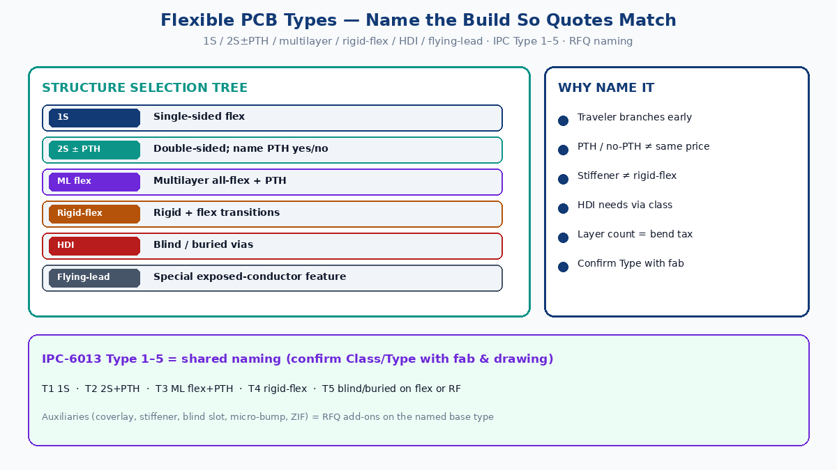
- Lock structure family first — single-sided (1S), double-sided with or without PTH (2S ± PTH), multilayer all-flex, rigid-flex, HDI with blind/buried vias, or flying-lead as a special exposed-conductor feature. Do not RFQ “flex, N layers” with construction TBD.
- Treat layer count as a bend tax — every added copper/dielectric plane raises bending stiffness roughly with thickness cubed in beam terms; more layers also push vias and coverlay steps into the hinge unless you design them out. Thicker is not “more reliable flex.”
- Call auxiliaries as RFQ add-ons — coverlay openings, stiffener islands, blind slots / windows, micro-bump arrays, ZIF finished thickness — each changes CAM and price; name them separately from the base structure type.
- Use IPC-6013 Type 1–5 as shared naming — Type 1 single-sided flex; Type 2 double-sided flex with PTH; Type 3 multilayer flex with PTH; Type 4 rigid-flex with PTH; Type 5 flex or rigid-flex with blind and/or buried vias. Confirm Type and Class with fab and drawing — Types are communication aids, not silent plant defaults.
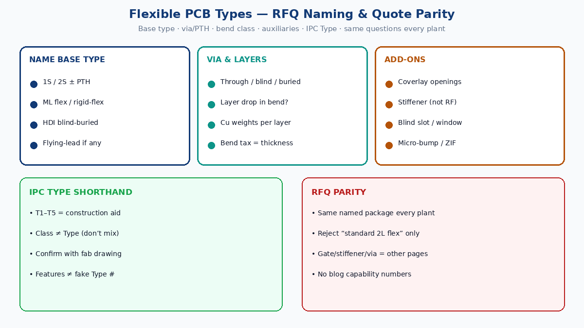
- Issue one named RFQ package to every plant — structure type, layer count and PTH/via class, bend class (static vs dynamic — detail in specialized playbooks), auxiliaries, stack sketch, and the same questions to each fab so quotes share assumptions.
Factory tip: “2-layer flex” without “with PTH / without PTH / rigid islands / blind vias / flying lead” is not a build name. Plants will quote shop habit and your first article will reveal what they assumed.
Why structure naming decides whether quotes match
China fab travelers branch early: whether copper exists on one face or two, whether holes are drilled and plated, whether rigid FR4 (or equivalent) is laminated into the stack, and whether microvias or buried vias exist. Each branch owns different drill, plate, laminate, and inspection steps. Price, lead time, and yield risk follow the traveler — not the buyer’s informal “flex board” label.
Typical mismatch: buyer meant 1S + stiffener, plant quoted 2S with PTH and put vias in the bend; drawing showed FR4 islands and plant priced rigid-flex; buyer needed Type 5 blind vias and got through-vias only; flying leads were coverlaid as “standard finish.” Name the build so process assumptions match the drawing — then compare price.
Structure selection tree (name the build)
| Shop / RFQ label | What it usually means | Typical use | Quote / CAM traps |
|---|---|---|---|
| 1S (single-sided) | Copper on one face of PI (or equivalent) flex; no PTH | Simple interconnect, LED strips, low-density tails | Easy to under-spec stiffener / coverlay; do not assume “1S” forbids local stiffener islands |
| 2S without PTH | Copper both faces; no plated holes — connection by edge, pads, or selective features | Some static interconnects where vias are forbidden in bend | Rare vs PTH 2S; confirm how faces connect; do not assume free vias |
| 2S with PTH | Double-sided flex with plated through-holes | Most production double-sided FPC | Via location vs bend is the reliability killer — via/bend detail is a specialized playbook |
| Multilayer flex (all-flex) | Three or more flex copper layers with PTH (often Type 3) | Density without rigid sections | Bend stiffness rises fast; keep vias and thick stacks out of hinges |
| Rigid-flex | Rigid material + flex laminated as one product with designed transitions (often Type 4) | Connector/SMT islands that need true rigid multilayer and PTH owned by rigid | Do not RFQ as “flex + thick FR4 stiffener” when you need rigid multilayer circuitry |
| HDI blind / buried | Flex or rigid-flex with blind and/or buried vias (often Type 5) | Fine-pitch / BGA / dense escape on flex or RF | Via class and stack must be on RFQ; “HDI” alone is not a stack |
| Flying-lead (special) | Exposed conductors without coverlay at designated ends / windows | Bonding, battery tabs, selective contact | Not a separate IPC Type number — call it as a feature on the named base type |
Selection order: one face or two? plated holes — and where vs bend? three-plus flex layers or local rigid multilayer? blind/buried or through only? flying leads / selective openings? Answer before price sheets. The flex PCB sourcing gate owns bend class and pure / stiffened / rigid-flex family; this map names the layer/via structure so quotes match.
Why layer count kills bend stiffness
Flexible copper-clad constructions behave like thin beams in the hinge. Bending stiffness scales strongly with thickness (classic plate/beam intuition: stiffness rises with thickness cubed for a given modulus and width). Adding layers does three things at once:
- Adds dielectric and copper thickness in the bend if those layers run through the hinge.
- Adds plated copper in vias if vias sit in or near the bend — local hard spots.
- Adds coverlay / adhesive steps at openings and layer transitions that concentrate strain.
A four-layer all-flex ribbon often feels board-like in a tight fold even with soft polyimide: density bought, stiffness inherited. Factory practice is to thin the bend — drop layers through the hinge where process allows, keep copper weight low in the dynamic zone, keep vias out of the designed bend. Bend multipliers, RA vs ED copper, and cycle methods belong in bend-radius / dynamic-materials playbooks. Rule here: more continuous layers through the hinge = higher bend tax. Confirm stack and bend map with fab — do not invent XFPCB capability numbers.
| Structure move | Bend effect (qualitative) | RFQ note |
|---|---|---|
| 1S thin Cu through hinge | Lowest stiffness class among common builds | Still name coverlay and any stiffener edge |
| 2S with Cu both faces through hinge | Higher stiffness; imbalance if one face heavier | Call copper weights per layer |
| Multilayer continuous through hinge | Stiffness rises quickly | Prefer layer drop / window in bend if density allows |
| PTH / microvia in bend | Local hard point; crack risk | Keep-out from bend — detail in via/dynamic playbooks |
| Rigid island at bend edge | Modulus cliff | Stiffener / rigid-flex edge keep-out — specialized playbooks |
Auxiliary structures as RFQ add-ons (not base types)
These are features on a named base structure — not substitutes for naming 1S / 2S / multilayer / rigid-flex / HDI:
| Add-on | What the fab must know | Where deep DFM lives |
|---|---|---|
| Coverlay openings | Opening size, registration, adhesive squeeze-out, solder-mask vs coverlay regions | Coverlay opening accuracy playbook |
| Stiffener | Use-case, material, adhesive class, side, edge keep-out | Stiffener applications playbook |
| Blind slot / window | Controlled depth or selective layer removal for bend or access | Confirm process with fab; do not assume laser/route habit |
| Micro-bump array | Height, pitch, pad stack, inspection | Micro-bump array playbook |
| ZIF / FFC tail | Finished insert thickness, contact side, pad geometry | ZIF/FFC connector-tail playbook |
| EMI shield film / ground stitch | Coverage, ground vias, opening map | EMI / RF specialized notes where applicable |
RFQ line that says “flex with stiffener and coverlay” without base type is still incomplete. RFQ that names Type 2, 2S with PTH, static install, FR4 stiffener PSA opposite pads, coverlay openings per drawing can be priced by more than one plant on the same assumptions.
IPC-6013 Type 1–5 as shared naming language
IPC-6013 is the industry performance specification family for flexible printed boards. Buyers and fabs use Type numbers as a short hand so “double-sided with PTH” and “rigid-flex with blind vias” are not reinvented in email slang. Treat Types as a communication aid — always confirm Type, Class (product class / acceptance), and the actual stack on the fab drawing and PO.
| IPC-6013 Type (common buyer shorthand) | Construction idea | Aligns with shop labels |
|---|---|---|
| Type 1 | Single-sided flexible printed board | 1S |
| Type 2 | Double-sided flexible printed board with plated through-holes | 2S with PTH |
| Type 3 | Multilayer flexible printed board with plated through-holes | Multilayer all-flex |
| Type 4 | Multilayer rigid and flexible material combinations with plated through-holes | Rigid-flex |
| Type 5 | Flexible or rigid-flex multilayer constructions that include blind and/or buried vias | HDI blind/buried on flex or rigid-flex |
Use Types without overclaiming: write Type plus a plain line (e.g., “IPC-6013 Type 2 — double-sided flex with PTH — static bend class”). Separate Class (acceptance) from Type (construction) — do not say “Class 3” when you meant “Type 3 multilayer.” Confirm Type 5 when you need blind/buried; some “HDI” quotes are through-vias only. Flying-lead, stiffener, coverlay windows, and micro-bumps are features on a Type — not fake Type numbers. Confirm class/type with fab and drawing; blog tables are not the IPC document or a capability letter.
RFQ naming checklist (so quotes share assumptions)
Send every plant the same named package:
- Base structure name — 1S / 2S without PTH / 2S with PTH / multilayer flex / rigid-flex / HDI blind-buried; plus IPC Type 1–5 shorthand if you use it.
- Layer count and copper weights — per flex (and rigid) layer; note any layer drop in the bend.
- Via class — through only; blind; buried; microvia rules; via keep-out from bend (point to via/dynamic playbooks for detail).
- Bend class — static install vs dynamic cycle life statement (gate / bend-radius / materials playbooks own the numbers — name the class here).
- Auxiliaries — stiffener / coverlay openings / blind slots / micro-bump / ZIF / shield — each named or marked N/A.
- Flying-lead or selective exposed copper — yes/no, locations, finish.
- Stack sketch or controlled stack-up — materials called as families; thickness bands marked “confirm with fab.”
- Same process questions to every plant — which Type they will run, whether stiffener is bonded island vs true rigid-flex, whether blind vias are in scope, FAI checks for openings and thickness.
Reject quotes that only say “standard flex” or “2L FPC” with no via/PTH/rigid/HDI line.
Boundaries — specialized playbooks (do not merge)
Keep this map thin. Point to specialized playbooks instead of rewriting them: flex PCB sourcing gate; stiffener applications; coverlay opening accuracy; micro-bump arrays; ZIF/FFC tails; bend radius / dynamic life and dynamic materials; double-sided via design and dynamic bending; rigid-flex DFM and bend-failure; RF flex design / RF bend-fail. Mention only as boundaries so this page stays the name-the-build map.
Closing
Quotes match when the build has a name: structure family, via/PTH class, IPC Type shorthand confirmed with fab, auxiliaries called out, bend class stated. Layer count that runs through the hinge buys density and spends stiffness — design the hinge thin on purpose. Use IPC-6013 Type 1–5 to talk to plants, then lock the same named RFQ on every quote. Confirm class, type, and stack with the fab and drawing — never paste blog figures as XFPCB capability numbers.