

Every assembly supplier that wants aerospace or other high-reliability work shows a list of machines. Modern placement heads, multi-zone reflow ovens, 3D inspection, X-ray. The list is not irrelevant; some jobs cannot be done without capable equipment. But when an assembly fails in the field and the investigation begins, nobody asks what brand the oven was. They ask what the oven actually did to that board on that day, which components went onto it from which lots, whether the inspection system was set up to catch the defect, and whether the machine was in calibration.
That is the useful way to think about equipment for high-reliability PCB assembly: not as a capability claim but as a source of evidence. A machine earns its place in an aerospace-intent build when it controls a process tightly and leaves a record that proves it did. This article looks at the main equipment on a high-reliability assembly line through that lens, from our perspective as a Shenzhen PCBA factory, and describes what buyers should ask to see.
A note on scope: equipment is only one piece. Certified quality management (such as AS9100 where your program requires it), workmanship to IPC-A-610 Class 3 and J-STD-001 with its space addendum where applicable, trained operators and the right drawings all matter as much. We cover certification and fabrication-versus-assembly responsibilities in other guides; here the question is what the equipment itself should contribute.
Traceability starts at the feeder
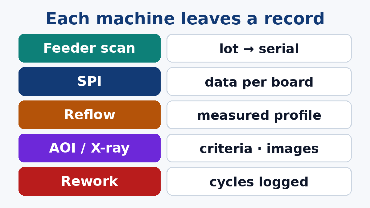
The single most valuable capability for high-reliability work is not a machine but the link between machines: the ability to say, for any serialized board, which component lot and reel went into each reference designator.
That link is made at material handling and placement. Each reel is labeled when it is received, the label is scanned when it is loaded onto a feeder, the feeder is verified against the placement program, and the placement machine records which feeder supplied each placement on each board. Automated storage and a manufacturing execution system tie those records together.
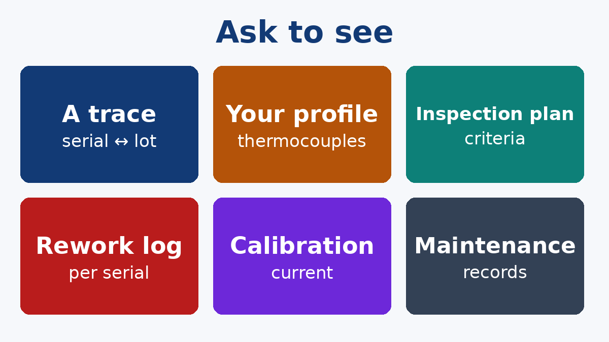
What to ask for: a demonstration of a trace from a board serial number back to component lots, and from a component lot forward to every board that used it. The second direction matters more in practice: when a component maker issues an advisory, you need to find every affected assembly quickly.
Paste printing and SPI: data, not just detection
Most solder joint defects start at the printer. For high-reliability work, the printer needs repeatable alignment and consistent paste release, and SPI must measure every deposit on every board.
What elevates this from detection to control is how the data is used. SPI results should be stored per board, trends monitored, and the printer corrected when deposits drift, before defects occur. Stencil life, cleaning frequency and paste handling (time out of refrigeration, time on the stencil) should be tracked.
What to ask for: SPI records linked to board serials, the rules for when a board is washed and reprinted, and paste handling records.
Placement: accuracy that is verified
Placement machines handle everything from very small passives to large BGAs and odd-form parts. For high-reliability work, the interesting questions are how placement accuracy is verified over time and how component recognition catches wrong or damaged parts.
Machines should be on a preventive maintenance schedule with periodic accuracy verification, using a calibration board or similar method, and the results recorded. Vision systems should check component presence, orientation and lead condition before placement, and the rejection data is itself useful evidence of component quality.
What to ask for: maintenance and accuracy verification records for the machines that would build your boards, and how the line handles a part the vision system rejects repeatedly.
Reflow: the profile on your board, not the oven setting
An oven's zone setpoints are not the thermal profile your board sees. The profile depends on the board's mass, copper distribution, component mix and conveyor speed. For high-reliability work, the profile must be measured on an actual assembly, with thermocouples attached at representative locations including the largest thermal mass and the most sensitive component, and checked against the solder paste specification and component limits.
Once established, the profile must be controlled. Ovens with continuous monitoring can record that each board passed through within limits. Nitrogen atmosphere can improve wetting for some processes. Vacuum reflow or vapor phase soldering may be justified where voiding in large thermal pads or BGAs is critical; they are tools for specific problems rather than general upgrades.
What to ask for: the measured profile for your assembly, with thermocouple locations, and how oven performance is monitored between profile runs.
Inspection: coverage and settings, documented
Automated optical inspection and X-ray are central to Class 3 builds, but their value depends entirely on how they are programmed and what criteria they apply.
For AOI, ask how the program for your board was built and validated, what defect types it is set to detect, and how calls are reviewed. For X-ray, ask which components are inspected, whether the system measures void percentage, and what criteria are applied. Systems used for X-ray inspection of BGAs and bottom-terminated components should store images for your records.
Inspection equipment should also be verified, for example with known reference samples, so that a drift in detection is caught.
What to ask for: the inspection plan for your assembly, sample images from first article, and the criteria in use.
Through-hole, selective soldering and rework
Many high-reliability assemblies are mixed technology, with connectors and larger parts soldered through-hole. Selective soldering machines with programmable paths, controlled preheat and nitrogen give far more repeatable results than manual soldering on critical joints, and the program becomes part of the record.
Rework is where uncontrolled processes most often creep in. For Class 3 work, rework of area-array components should be done on dedicated rework stations with profiled heating, not with hand tools, by certified operators, and recorded against the board serial. Limits on the number of rework cycles should be defined.
What to ask for: selective solder programs for your connectors, and the rework procedure and records.
Cleaning and contamination
Flux residues and other contamination can cause corrosion and leakage currents, particularly under conformal coating and in humid environments. If your assemblies are cleaned, the cleaning process should be validated for your board, including under low-standoff components, and cleanliness verified by an agreed method, such as ionic contamination testing or the more discriminating methods described in IPC standards for cleanliness assessment.
What to ask for: the cleaning process and how its effectiveness is verified on your assembly.
Conformal coating
Coating protects assemblies from moisture and contamination, but only if it covers the right areas at the right thickness and stays off connectors and test points. Selective coating machines with programmed paths give repeatable coverage. Coatings with UV tracers allow full inspection under UV light.
What to ask for: coating thickness measurement method and results, and UV inspection records.
Test equipment and calibration
Flying probe or in-circuit test and functional test confirm electrical performance. For high-reliability work, test programs and fixtures should be under revision control, and every measurement instrument, from multimeters to X-ray systems and torque drivers, should be on a calibration schedule with traceable records.
What to ask for: calibration status of the equipment that will test your boards, and the test program revision used.
Maintenance: the quiet part of reliability
Equipment that is not maintained drifts. Preventive maintenance based on schedules and, increasingly, on machine data, keeps placement accuracy, oven performance and inspection sensitivity within limits and avoids unplanned downtime in the middle of a critical lot. Maintenance records are rarely requested by buyers, which is exactly why they are revealing.
Putting it into your requirements
For an aerospace-intent or other high-reliability assembly, your purchase order and quality agreement can make equipment evidence explicit:
- Serial-level traceability to component lots, with forward and backward trace capability.
- SPI on all deposits, with data retained per board.
- A measured reflow profile for the assembly, with thermocouple locations and approval before production.
- AOI and X-ray per an agreed inspection plan, with criteria and image retention.
- Controlled rework on dedicated equipment with recorded cycles and limits.
- Cleaning validation and cleanliness verification where applicable.
- Coating thickness and UV inspection records where applicable.
- Calibration and maintenance records available on request or during audit.
The data retention period should match your program's requirements, which in aerospace can be long.
Our PCB Assembly Capability page lists what our lines handle. For a high-reliability program, the more useful conversation is about which of the records above we would produce for your assembly and how you would receive them; send us your requirements and we will answer line by line, including anything we would not be the right supplier for.