
A printed circuit board (PCB) or assembled board (PCBA) is bad when unpowered inspection or resistance checks show burned laminate, rail-to-ground shorts, opens on critical nets, or intermittent continuity that matches the field symptom -- before any full-voltage power-on. Start cold: look, smell, magnify, then meter. Separate PSU, cable, and firmware failures from board faults so you do not scrap a good assembly or finish a short into deeper carbonization. Buyers use the same triage to cut downtime and to document CM warranty claims with photos and meter readings, not guesses.
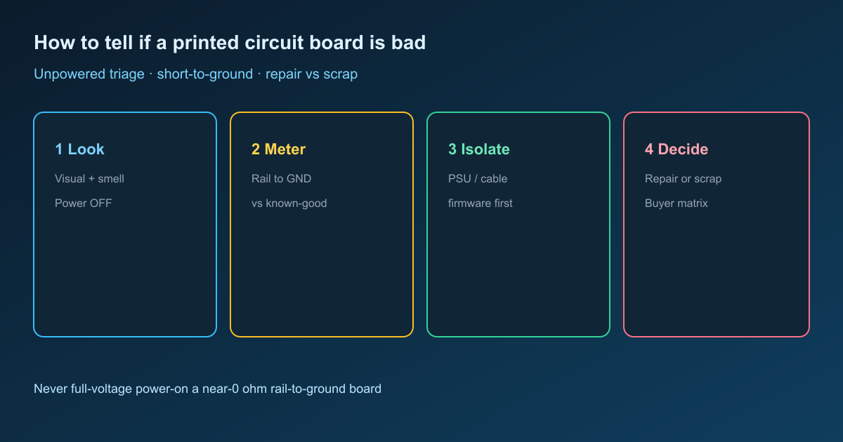
Symptom to meaning: what the board is telling you
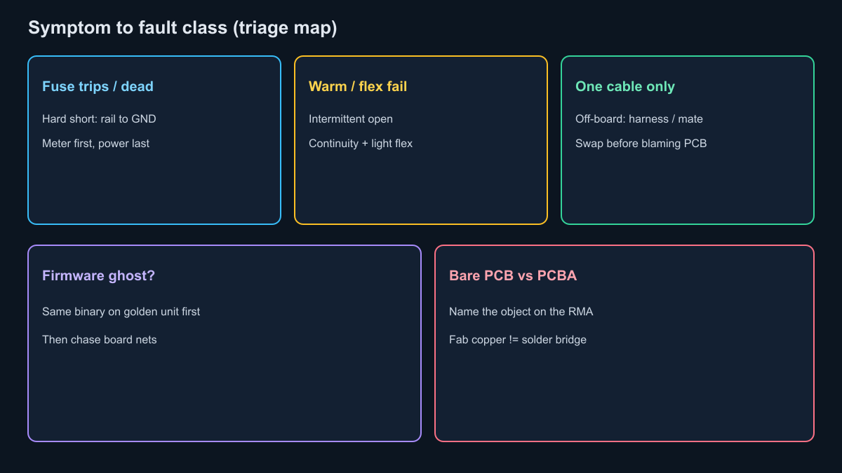
Match the field complaint to a fault class before you power anything: no-boot and repeated fuse kills often track rail-to-ground shorts; random resets with temperature track cracked joints; a unit that dies only with one cable points off-board first.
| Symptom (field or bench) | Likely meaning | Board vs not-board first check |
|---|---|---|
| Dead on connect; fuse or breaker trips immediately | Hard short on a supply net or reverse polarity damage | Unpowered ohms from each supply pin to GND; swap known-good PSU last |
| Boots, then browns out under load | Soft short, weak rail, failing input caps, or undersized path | Rail-to-GND resistance vs known-good; inspect electrolytics and connectors |
| Works after cool-down; fails when warm or after flex | Intermittent open (solder fatigue, via crack, connector) | Continuity on suspect net while gently flexing; do not "wiggle under power" |
| Random resets; one firmware load fails, another boots | Firmware or configuration until hardware is cleared | Same binary on a known-good unit; only then chase board nets |
| Fails only with one harness or dock | Cable, pinout, or mating connector -- not the PCB core | Swap cable and mate; inspect pin crush and shell ground |
| Smell of burnt flux or electrolyte; dark mask near regulators | Prior over-current or thermal abuse already started | Stop power-on; photograph; meter before any current-limited attempt |
| Bare board fails flying probe / ET; assembly "looks fine" | Fab open/short or assembly defect -- different owners | Name bare PCB vs PCBA on the RMA; do not blame fab for a solder bridge |
Bare boards and assemblies are not the same triage job. A bare PCB is judged by copper continuity and isolation. A PCBA adds parts, paste, and firmware. Label which object failed on the traveler so the CM and the fab do not argue past each other.
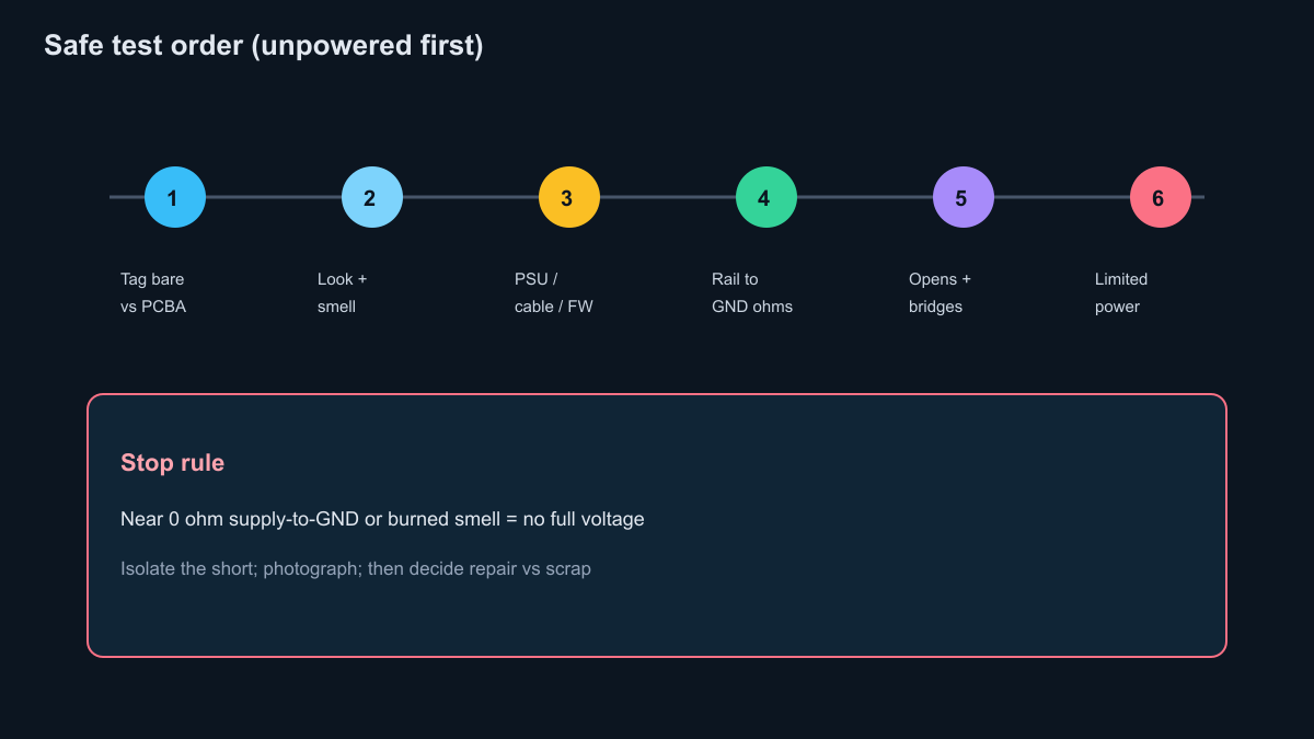
Safe diagnostic sequence (unpowered first)
Power-on is step six or later, never step one: a shorted rail under full voltage can carbonize laminate in seconds and wipe the evidence you need for a warranty claim.
- Identify the object. Write "bare PCB" or "PCBA" on the tag. Record serial, lot, and the exact symptom in one sentence.
- Visual + smell, power off. Good light and a loupe. Scan both sides for char, cracked packages, bulged caps, lifted pads, warp, and corrosion. Acrid or fishy odor means stop -- energy already went somewhere wrong.
- External suspects first. Swap or meter the PSU output unloaded, reseat or replace the cable, and confirm the same firmware/binary on a known-good unit when the symptom is "won't boot" or "config lost."
- Rail-to-ground resistance (DMM). Board unpowered, discharges complete. Measure each supply net to GND at the connector or test point. Compare to a known-good board of the same revision. Near-zero ohms on a rail that should read kilo-ohms (or the known-good value) is a hard stop.
- Neighbor and net continuity. Check adjacent pins for solder bridges. Check critical nets end-to-end for opens at connectors, flex zones, and heavy parts.
- Current-limited power only after isolation. If resistance looks sane, bring up with a limited supply and a clear trip plan -- not wall voltage into an unknown short. Scope probing a live shorted rail is how you enlarge the burn.
⚠️ Safety: Never apply full system voltage to a board that still smells burned or that reads near 0 ohm from supply to ground. Isolate the short first. A "quick power check" can turn a local part failure into multilayer scrap and erase the photo evidence your CM dispute needs.
💡 Procurement note: For CM warranty fights, attach unpowered photos, rail-to-GND readings vs a known-good serial, and whether the fault is bare-board copper or assembly. Vague "board bad" tickets get rejected; meter numbers and revision-matched comparisons do not.
Shorts: rail-to-ground method that actually isolates
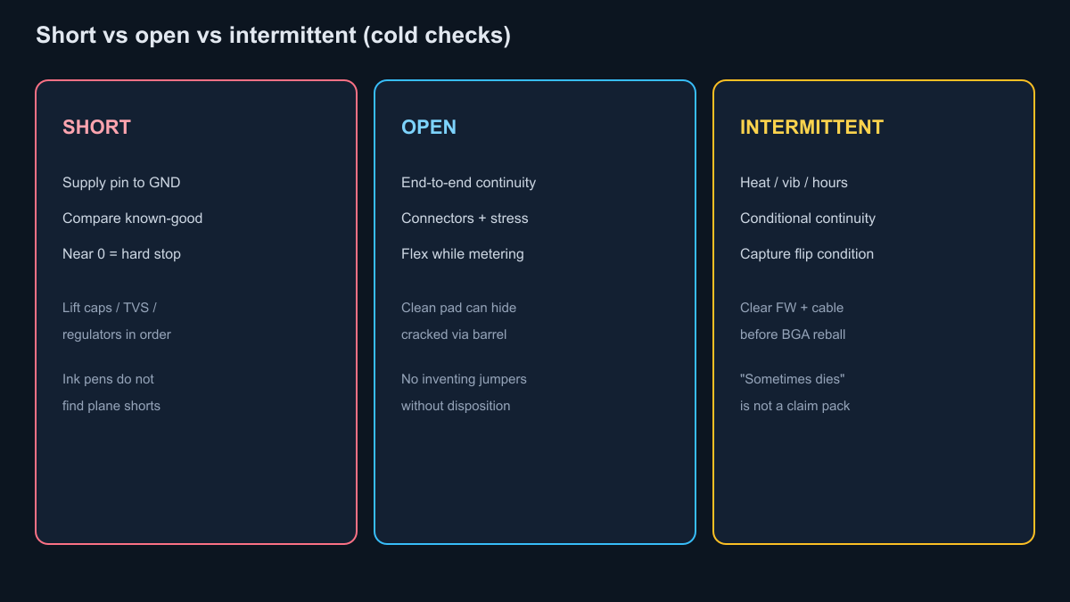
A short is confirmed by low resistance between nets that must stay isolated -- usually supply to ground -- not by hoping a conductive pen "finds" 0 ohm on a painted path.
With power removed, set the DMM to resistance (or diode mode as a second pass). Probe the supply pin and a solid GND reference on the same connector. Note the reading. Compare to a known-good board: many digital rails sit in the tens to hundreds of ohms from semiconductor loading; a true dead short collapses toward zero. If you have a current-limited supply and the rail is cleared for a brief, capped current, a thermal camera or careful fingertip check (after training) can highlight the hot part -- still not a full-voltage gamble.
Isolate by lifting likely suspects in order of probability: input capacitors, TVS diodes, regulators, then denser ICs. Mark each lift on the traveler. Neighbor-pin bridges at fine-pitch packages are common after rework; check them under magnification before you blame an internal plane short.
Conductive ink or "0 ohm" pens are oversold for this job. They can bridge a broken outer trace for a temporary continuity experiment on a non-critical net. They do not locate plane shorts, do not restore plating inside a via, and do not belong on a production disposition as a repair. Use them as a lab hack at most -- never as proof the board is fixed.
Opens: continuity without inventing jumpers
An open shows as missing continuity on a net that a known-good board carries end to end -- often at connectors, cracked fillets, or fatigued vias -- and it is confirmed cold before any jumper experiment.
Probe from connector pin to destination pad with power off. Wiggle the board gently at mounting points and cable entries while watching the meter; an intermittent open that chatters with flex is a mechanical story. Magnify dull or cracked fillets on heavy connectors and magnetics. On multilayer boards, a clean surface pad can still hide a cracked barrel -- if sister serials fail the same RefDes after rework heat, stop swapping parts and escalate to remake discussion.
Do not invent jumper routes without engineering disposition. Restoring the approved BOM joint is rework; adding a new conductor path is repair and needs authority on the traveler.
Intermittent faults: temperature, flex, and time
Intermittent boards fail under heat, vibration, or hours of run time while looking fine at first power -- treat them as conditional continuity, not as random firmware ghosts.
Work unpowered first: continuity under light flex, inspection at stress points, corrosion under shields and battery holders. If cold checks pass, a controlled thermal chamber or hot-air warm-up on a current-limited bench can reproduce the fault without a full field power cycle. Capture the condition that flips the meter: "open after 60 C," "brown-out after 10 minutes at 2 A load." That sentence is what procurement sends to the CM; "sometimes dies" is not.
Firmware still matters -- flash the same image on a golden unit before you authorize expensive rework. Cable pin maps matter -- one bent pin creates an intermittent that looks like a PCB open. Clear those before you approve a BGA reball on the wrong evidence.
Repair vs scrap decision matrix (buyers)
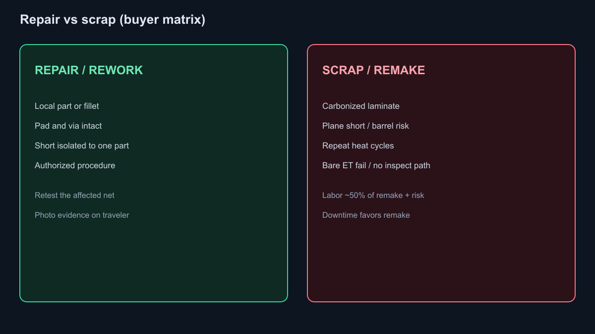
Repair when the fault is local, authorized, and verifiable; scrap or remake when laminate, vias, or unknown heat history make reliability unverifiable -- or when rework labor plus repeat risk exceeds remake lead time and downtime cost.
| Condition | Prefer repair / rework | Prefer scrap or remake |
|---|---|---|
| Single bulged cap or one cracked connector fillet; pad and via intact | Yes -- controlled remove/replace, then retest the net | No -- unless sister lots show the same signature from design |
| Near-0 ohm rail-to-GND isolated to one part | Yes -- after isolation and photo evidence | Escalate if short remains after lifts (plane or carbon path) |
| Charred mask, carbonized laminate, multilayer blister | No | Yes -- substrate integrity is already gone |
| Same RefDes failed after 2-3 heat cycles; barrel risk | Stop heating | Remake with RFQ notes on annular ring / via / copper |
| Bare-board ET fail (open/short in copper) | Usually no part-level fix | Remake or scrap bare PCB; do not assemble defects away |
| Labor + retest approaching ~50% of replacement PCBA cost | Rarely | Remake often wins once downtime and return risk are counted |
| Contract forbids the repair method; no X-ray for required hidden joint | Do not ship "fixed" | Scrap or return for MRB / remake |
Downtime math belongs on the same sheet as labor. A two-week remake that restores a production line can beat three days of heroic rework that fails again in the field. Warranty language matters: if the CM owns assembly defects, your triage photos and rail readings are the claim package. If the fab owns bare-board ET escapes, say "bare PCB" on the RMA -- not "assembly failed."
Incoming RMA / field return photo checklist
Ship the claim with cold evidence: photos and meter numbers beat a verbal "board is bad" every time the CM or fab pushes back.
Before cleaning or powering:
- [ ] Tag: bare PCB vs PCBA, serial, lot, revision, date code
- [ ] One-sentence symptom + duty (load, temperature, hours)
- [ ] Both sides of the board in focus (full board + close-ups of damage)
- [ ] Connector faces, cable ends, and PSU label if implicated
- [ ] Rail-to-GND resistance table vs a known-good serial (same rev)
- [ ] Smell / char notes; do not wipe carbon before photos
- [ ] Firmware version and whether a golden unit passes the same binary
- [ ] Prior rework count on the same RefDes if known
- [ ] What you already swapped (PSU, cable) and the result
Hand that pack to QA or purchasing before anyone "just tries power one more time." Triage that starts unpowered keeps scrap decisions honest and keeps shorted boards from becoming larger scrap.
Related XFPCB guides
- PCB repair or replace: warning signs -- field visual cues and remake RFQ notes after you finish triage
- Circuit board repair and PCB failure -- rework heat-cycle budget and scrap triggers once repair is chosen
- PCB inspection methods guide -- SPI, AOI, X-ray, and electrical coverage for production gates
- PCB DFM: design for manufacturing -- design-side checks that reduce the next lot of field returns