
Dynamic bend on a double-sided flex PCB fails first at PTH/via barrels and copper imbalance in the bend window — not at a random “bad polyimide” lot. Cyclic strain concentrates on plated barrels that stiffen the stack, on dual-sided copper that thickens and offsets the neutral axis, and on coverlay or plating that was never told the zone must stay flexible. Buyers who keep vias/pads/stiffeners out of the bend zone, force a single-conductor bend window, control coverlay balance and plating mask, and write bend-line / cycle / radius callouts into the China RFQ cut via-fatigue scrap before NPI.
This China-fab guide answers first: why PTHs crack in dynamic bend, how to define a single-copper bend window, plating-mask / selective-plate controls that stop copper thicken, coverlay and neutral-axis balance, drawing callouts that stick, and the RFQ matrix that makes flex quotes comparable. It is distinct from rigid double-sided board how-tos — here the product is FPC Type 2 under cyclic flex, not a FR-4 two-layer panel.
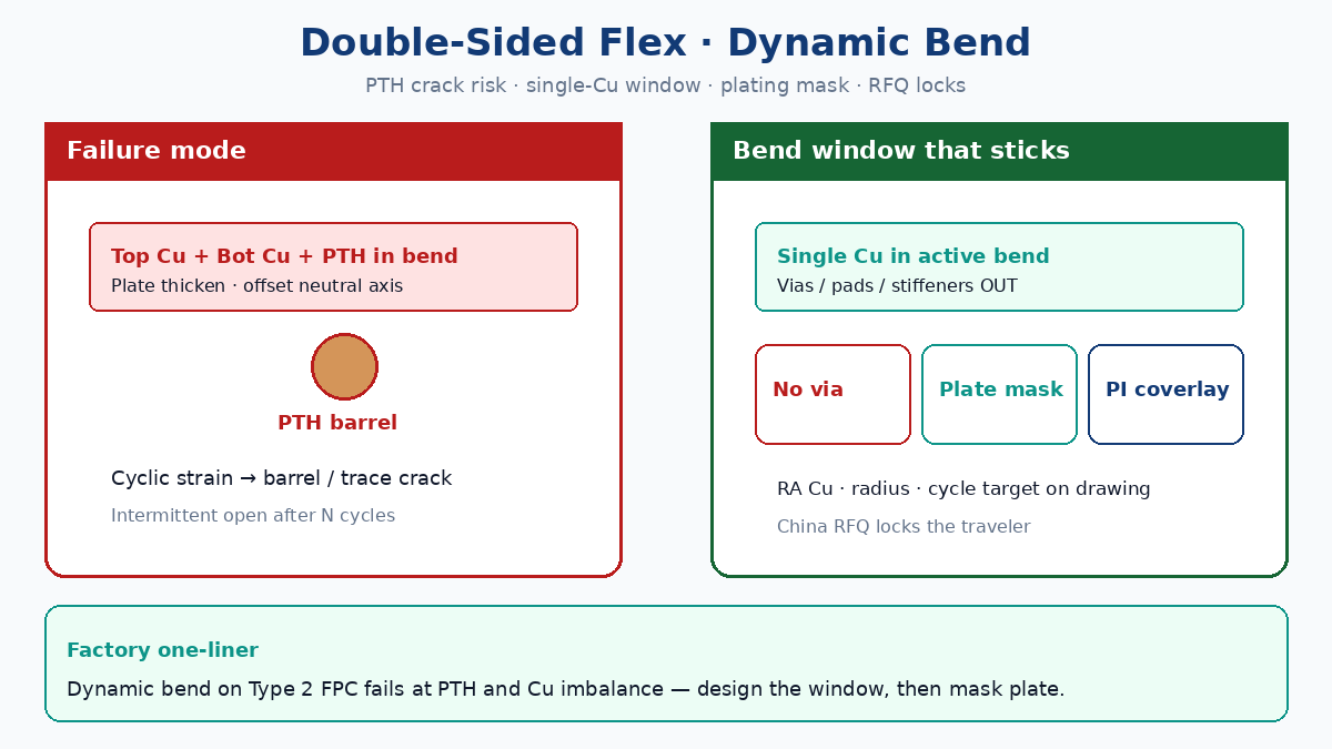
Answer first: dynamic bend fails at PTH and copper imbalance
| Term | Factory meaning | Why buyers care |
|---|---|---|
| Dynamic bend | Repeated flex to a radius / angle for a cycle-life target | Fatigue scrap, intermittent opens, field returns |
| Bend window / bend zone | Region that must flex; keep-outs for vias, pads, stiffeners | Silent DFM if only Gerber is sent |
| PTH / via in flex | Plated barrel connecting Top–Bot copper on Type 2 FPC | Barrel crack under cyclic strain — top failure mode |
| Single-conductor window | Ideally one copper layer (or carefully balanced Cu) in the active bend | Dual Cu + plate = stiffer, offset neutral axis |
| Plating mask / selective plate | Mask bend zone during panel plate so Cu does not thicken there | Prevents “flex that became semi-rigid” after PTH plate |
| Coverlay balance | Coverlay openings / presence managed so stack flexes about neutral axis | One-sided coverlay can shift stress into copper |
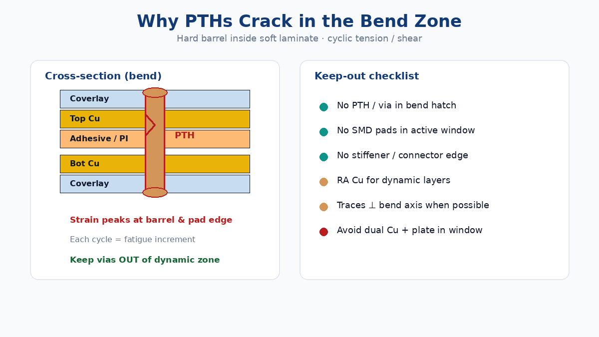
Double-sided FPC (IPC-6013 Type 2) needs vias somewhere for layer interconnect — but not in the dynamic bend zone. A plated barrel is a hard cylinder inside a soft laminate. Each bend cycle stretches outer copper and compresses inner copper; the barrel sees tensile and shear fatigue until resistance rises or the joint opens. Copper imbalance (both layers live in the bend, or plate builds extra Cu on top of traces) moves the neutral axis and raises peak strain. That is the Information Gain competitors often state as rules — China fabs need those rules wired into CAM and the traveler, not only into a design checklist.
Related rigid-flex bend geometry: bookbinder rigid-flex bend reliability. Functional flex context: functional flex PCB.
💡 Procurement Pro-Tip: If the quote reply says “double-sided flex, standard plate” with no bend-zone mark, assume the fab will plate the whole panel like a rigid Type 2. Force a bend-zone keep-out + plating-mask line on the RFQ before you compare unit price.
Why PTHs crack in the bend zone
| Mechanism | What happens on the line | Buyer symptom |
|---|---|---|
| Barrel fatigue | Cyclic tension/shear on plated Cu wall | Open / intermittent after N cycles |
| Pad crater / lift | Pad and barrel interface stressed at coverlay edge | High resistance at via nets |
| Local stiffness island | Via + annular ring + plate thicken resists flex | Crack starts at via perimeter, then runs into trace |
| Dual-sided Cu in bend | Both layers contribute stiffness; neutral axis shifts | Trace crack on outer bend face |
| Coverlay step / opening edge | Abrupt thickness change concentrates strain | Crack at coverlay window edge |
Design rules that stick in CAM:
- No vias, pads, or stiffeners in the dynamic bend zone. Park interconnects in static regions or rigidized areas.
- Prefer RA (rolled annealed) copper for dynamic flex; ED copper is a static/install-bend compromise.
- Route conductors perpendicular to the bend axis where possible; avoid abrupt width changes and 90° corners in the window.
- Keep stiffener edges and connector zones outside the cyclic region — transition fillets belong at the rigid/flex or stiff/flex boundary, not mid-bend.
This article does not replace how double-sided PCB works (rigid double-sided FR-4). Rigid Type 2 plating habits are exactly what break dynamic FPC if copied blindly onto flex.
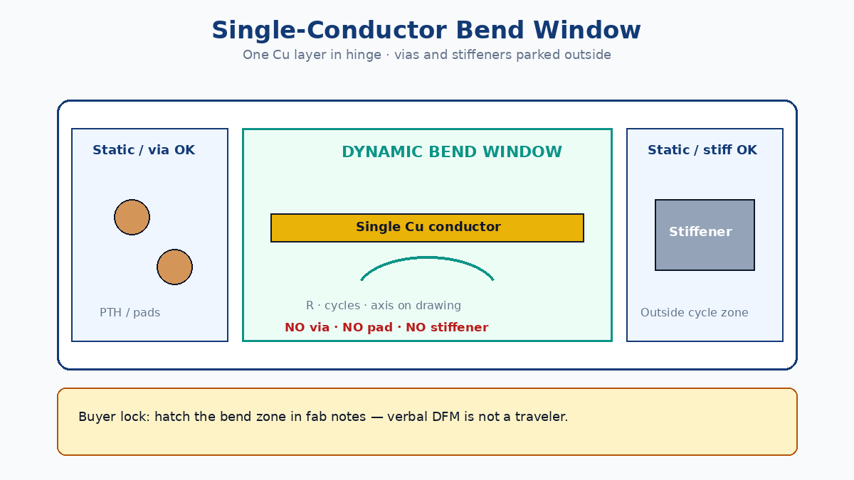
Single-copper bend windows (and when dual Cu is unavoidable)
Ideal dynamic window on a double-sided FPC: one copper layer carries the nets in the bend; the opposite copper is cleared or never patterned there. That keeps thickness down and the neutral axis closer to the remaining conductor.
| Construction choice | When to use | Fail mode if ignored |
|---|---|---|
| Single Cu in bend window | Most dynamic hinges, cable replacements, scanner heads | Dual Cu + vias → early fatigue |
| Staggered / fingered dual Cu | Rare nets that must exist on both faces outside active radius | Overlapping Cu both faces in same bend line |
| Thinner Cu (e.g. 1/2 oz / 12–18 µm RA) | High cycle life at given radius | Spec “1 oz both sides” for convenience |
| Adhesiveless PI where justified | Thin stack, high cycle, tight radius | Adhesive stack too thick for radius target |
| Bend radius lock | ≥ fab + IPC-2223 guidance for layer count / cycle class | “As small as possible” with no number |
Rule of thumb buyers put on drawings (confirm with fab for the actual stack thickness T): static bend often ~6–10×T; dynamic bend multipliers rise with layer count and cycle target — double-sided dynamic commonly needs a larger radius than single-sided. Do not paste a single-sided radius onto a plated Type 2 stack.
⚠️ Factory callout: “Single-sided bend window on a double-sided FPC” must be drawn: copper clearances, coverlay openings, and no plate in window. Verbal DFM chat is not a traveler instruction.
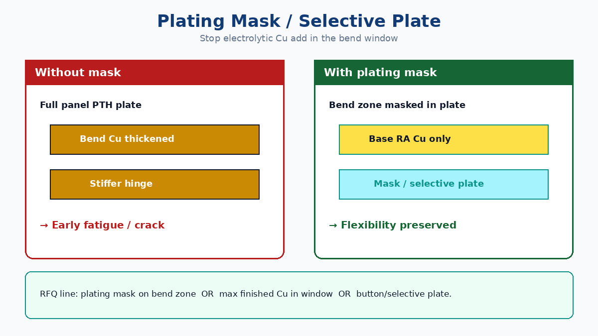
Plating mask / selective plate: stop copper thicken in the bend
Double-sided flex usually needs panel or pattern plating for PTHs. If the bend zone is left open to plate, traces and land remnants gain extra copper thickness. Stiffer copper = lower cycle life at the same radius.
| Process control | What to ask the fab | Why it matters |
|---|---|---|
| Plating mask / tenting of bend zone | Mask dynamic region during PTH plate | Blocks Cu buildup on bend conductors |
| Selective / button plate | Plate only via pads that must exist (outside bend) | Avoids full-panel Cu thicken |
| Finished Cu max in bend | Cap thickness on drawing (e.g. base + plate limit) | Quotes without a cap silently over-plate |
| Bend zone marked in Gerbers / fab drawing | Explicit layer or note: BEND — NO PLATE / NO VIA | CAM treats zone as rigid Type 2 otherwise |
| RA Cu callout | Foil type for dynamic layers | ED + plate is a fatigue stack |
China-fab practical note: not every shop runs the same selective-plate recipe. Put “plating mask on bend zone” or “no electrolytic Cu add in bend window” in the RFQ so Plant A and Plant B price the same process risk. If a plant cannot mask, they must propose an alternate stack (often single-sided flex or rigid-flex with bend in single-Cu region) — that is a design change, not a free DFM tweak.
EMI shield films and stiff covers also add stiffness; shield strategy belongs outside or carefully windowed around dynamic hinges — see flex PCB EMI shielding.
Coverlay balance and neutral axis
Coverlay (polyimide film + adhesive) is the flex equivalent of solder mask — and LPI solder mask is the wrong product in a dynamic bend. Coverlay thickness and openings move the neutral axis.
| Lever | Balanced practice | Scrap pattern when wrong |
|---|---|---|
| Coverlay both sides vs selective open | Match openings so Cu sits near neutral axis | One-sided heavy coverlay → outer Cu cracks first |
| Opposite-side coverlay trim | Sometimes open or thin coverlay opposite the conductor in bend | “Protect everything” → too stiff |
| Coverlay edge vs bend line | Keep abrupt coverlay steps out of peak strain line | Crack at coverlay window edge |
| No LPI in dynamic zone | Polyimide coverlay only in cyclic region | Mask cracks → Cu exposed → fatigue |
| Adhesive thickness | Thin, flex-rated systems for high cycle | Thick acrylic stack eats radius budget |
Buyer language that works: “Dynamic bend: polyimide coverlay; no LPI; coverlay openings per stack sketch; maintain neutral-axis balance.” Attach a simple stack cross-section for the bend region — one sketch prevents three EQ loops.
Material and application framing: advantages of flexible PCBs.
Drawing callouts that stick (bend line, cycles, radius, keep-out)
Gerbers alone do not define a dynamic hinge. Put these on the fab drawing / fab notes:
| Callout | Example intent | If missing |
|---|---|---|
| Bend line / bend axis | Centerline and bend direction | CAM guesses; stiffener placed wrong |
| Bend zone outline | Hatch or layer: dynamic keep-out | Vias sneak into window |
| Min bend radius | R ≥ … mm (or × thickness with T stated) | Assembled fixture tighter than fab assumed |
| Cycle life target | e.g. 10k / 100k / 1M cycles + angle | No acceptance test agreed |
| Keep-out | No via / pad / stiffener / connector in zone | Classic Type 2 plate-through habit |
| Cu & plate | RA Cu; plating mask / max finished Cu in bend | Over-plate fatigue |
| Coverlay | PI coverlay; LPI forbidden in bend | Mask crack returns |
| Test | Continuity / ΔR after flex test method | “Looks fine” visual only |
IPC references buyers may cite (confirm edition with fab): IPC-2223 design, IPC-6013 performance (Type 2), flex test methods such as IPC-TM-650 2.4.3 family. Citing class/type without bend geometry is incomplete.
China fab RFQ matrix: make quotes comparable
Paste into the quote package so every bidder prices the same fatigue risk:
| RFQ field | What to specify | Fail mode if missing |
|---|---|---|
| Construction | Double-sided FPC / IPC-6013 Type 2 (or stated type) | Quoted as rigid-ish flex |
| Dynamic vs static | Dynamic + cycle target + bend angle | Static radius used |
| Bend radius & thickness T | R and stack T for bend region | Fixture vs fab mismatch |
| Bend zone artwork | Marked keep-out; no via/pad/stiffener | Vias in bend after CAM |
| Copper | RA vs ED; weight; single-Cu window yes/no | ED + dual Cu fatigue |
| Plating control | Plating mask / selective plate / max Cu in bend | Full panel plate thicken |
| Coverlay | PI coverlay; balance / openings; no LPI in bend | Mask in hinge |
| Stiffeners / shields | Locations outside bend; FR4/PI/steel note | Stiffener edge in cycle zone |
| Acceptance | Flex cycle test + ΔR / open criteria | Scrap found at system test |
| Related EMI / shield | Windowed shield if any | Continuous shield kills flex |
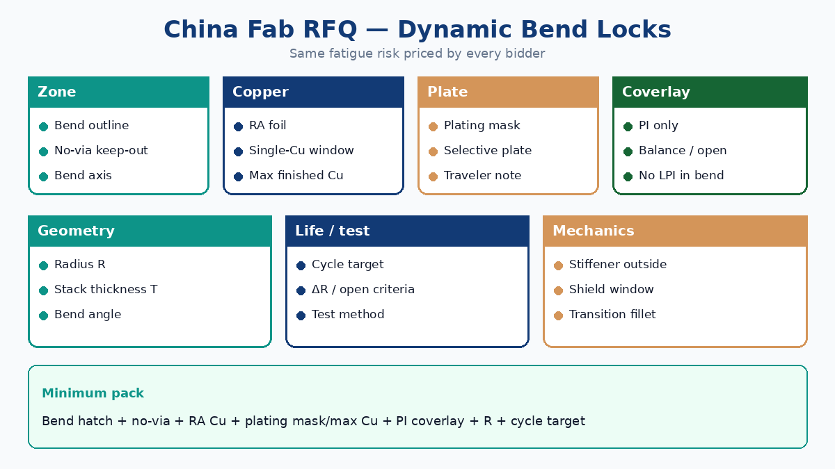
Minimum viable pack: bend-zone outline + no-via keep-out + RA Cu + plating-mask (or max Cu) + PI coverlay + radius + cycle target. Everything else is refinement.
Soft close for XFPCB buyers
If via cracks or intermittent opens already showed up on a double-sided dynamic hinge, send the bend sketch (radius, angle, cycles), stack intent for the window, and plating/coverlay notes with the Gerbers — not only “2-layer flex, best price.” XFPCB can review single-copper bend windows, plating-mask feasibility, coverlay balance, and put bend keep-outs on the traveler so production does not treat the hinge like a rigid Type 2 panel.
Start from the related flex primers linked above, then attach the RFQ matrix on this page so every China fab answers the same dynamic-bend questions.