
Plated through holes on a double-sided flex PCB connect Top–Bot copper, but electrolytic plating copper is brittle compared with rolled annealed (RA) foil. Buyers who chase “more plate for via reliability” without a flex budget often stiffen the stack, crack barrels in the bend zone, or force adhesiveless/HDI process they never quoted. Balance barrel integrity against flex life: control typical plating thickness (practice windows, not legal limits), choose adhesiveless vs adhesive laminate for HDI intent, decide when through + blind/microvia coexistence needs an early fab review, and lock stiffener/coverlay/finish and RFQ fields so vias stay out of trouble.
This China-fab guide is answer-first for Type 2 FPC via design — plating tradeoffs, materials, microvia notes, coverlay/stiffener buyer language, and an RFQ matrix. Bend-zone keep-outs and dynamic cycle rules live in the companion post double-sided flex PCB dynamic bending. Product capability context (not this blog slug): double-sided flex PCB manufacturing.
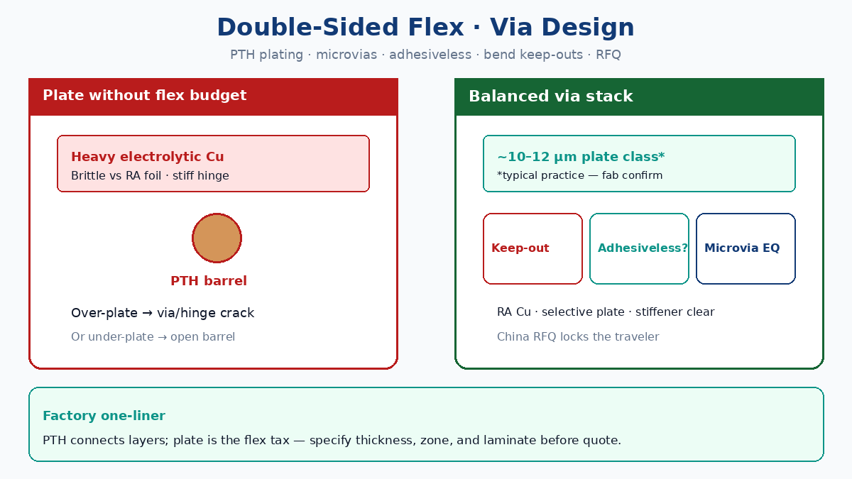
Answer first: PTH connects layers — plating copper is the flex tax
| Term | Factory meaning | Why buyers care |
|---|---|---|
| Double-sided flex / Type 2 FPC | Two Cu layers on PI with plated interconnect | Layer jump without rigid-flex cost |
| PTH / plated through hole | Drilled hole with electrolytic Cu barrel Top–Bot | Interconnect — also a stiffness island |
| RA foil vs plate | Rolled annealed base Cu vs electrolytic add | RA flexes; plate is grainier / more brittle |
| Typical plate window | Practice class ~10–12 µm barrel Cu (confirm with fab) | Under-plate = via risk; over-plate = flex risk |
| Adhesiveless laminate | Cu bonded to PI without acrylic adhesive core | Thinner stack, HDI-friendly; process/cost shift |
| Microvia / blind | Laser (or sequential) short via, often ≤0.15 mm class | Density — needs fab process window early |
| Bend keep-out | No via/pad/stiffener in dynamic or install bend hatch | Same rule as dynamic-bend post; vias belong static |
Double-sided flex needs vias somewhere. A plated barrel is a hard cylinder in a soft stack. Extra electrolytic copper improves annular integrity and aspect-ratio fill — until the same copper thickens traces, offsets the neutral axis, or sits inside a bend hatch and fatigues. The Information Gain is not “always plate thick” or “never plate”: it is state a finished Cu / barrel target, park vias outside bend zones, and match laminate (adhesive vs adhesiveless) to HDI and cycle intent before the China RFQ.
Related primers: functional flex PCB, advantages of flexible PCBs. Rigid double-sided how-tos (how double-sided PCB works) describe FR-4 panel plate habits — do not copy those blindly onto FPC.
💡 Procurement Pro-Tip: If the quote says “2-layer flex, standard PTH” with no finished Cu max, no bend keep-out, and no adhesiveless/adhesive callout, assume full-panel plate like a rigid Type 2. Force thickness + zone + material lines before you compare unit price.
Plating thickness: typical practice windows (not legal limits)
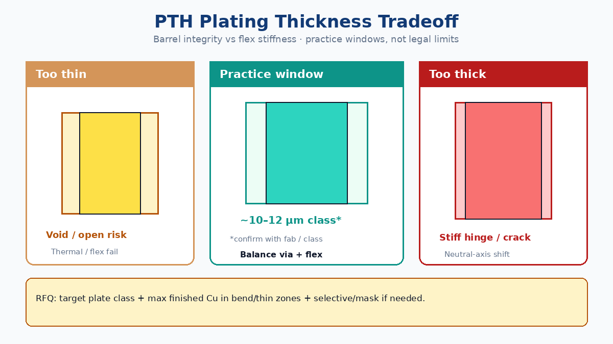
China fabs often talk barrel or average electrolytic Cu in a ~10–12 µm class for consumer/industrial Type 2 flex when aspect ratio and hole size are ordinary. That is typical practice language, not a statutory or IPC “legal” floor/ceiling you can paste as a warranty. Class 3, fine pitch, high aspect, or automotive quals may push thicker plate or different acceptance; ultra-thin dynamic hinges may need selective plate or button plate so the bend window does not inherit full panel add.
| Practice choice | Typical buyer intent | Fail mode if ignored |
|---|---|---|
| ~10–12 µm class plate (confirm) | Balance barrel integrity vs flex on standard Type 2 | Guessed “standard” varies plant to plant |
| Min barrel Cu on drawing | Via reliability / continuity after thermal stress | Thin barrels open in reflow or flex |
| Max finished Cu in bend / thin areas | Preserve hinge flexibility | Over-plate → early fatigue (see dynamic post) |
| Selective / button / plating mask | Plate vias outside bend; spare bend conductors | Full panel plate thickens hinge Cu |
| Aspect ratio callout | Hole dia vs stack thickness | Deep small holes under-plate or void |
| RA base foil + controlled plate | Dynamic or high-flex nets | ED + heavy plate fatigue stack |
Buyer language that sticks: “Finished electrolytic Cu in PTH: target class ~10–12 µm (fab confirm); max finished Cu in bend window = …; plating mask / selective plate on hatch …” Numbers without zone context still get misapplied.
Adhesiveless vs adhesive laminate for HDI flex
Adhesive-based double-sided flex uses acrylic (or similar) bond plies between Cu and PI. Adhesiveless constructions bond Cu more directly to PI — thinner dielectric, better dimensional behavior for fine features, and a common path when laser microvias or tight registration matter.
| Laminate path | When buyers choose it | Watch-outs |
|---|---|---|
| Adhesive (acrylic) Type 2 | Cost-sensitive, looser pitch, static/install bend | Thicker stack; adhesive Tg/flow; HDI limits |
| Adhesiveless PI | HDI, microvia, tight bend budget, thinner T | Higher material cost; fab capability matrix |
| Hybrid notes | Adhesiveless in flex, other builds elsewhere | Must be explicit on stack table |
| Cu type | RA for dynamic; ED often static/install | Foil + plate interaction still applies |
| Coverlay system | Match adhesiveless process window | Wrong coverlay adhesive = delam / EQ |
Do not pretend every China shop runs adhesiveless HDI flex equally. Put adhesiveless yes/no, target thickness T, min microvia / capture pad rules, and registration class on the RFQ. If the design is “maybe HDI later,” freeze the stack now — swapping adhesive → adhesiveless mid-NPI changes impedance, bend radius, and drill/laser recipes.
⚠️ Factory callout: “HDI flex” without adhesiveless/adhesive, microvia type, and stack T is not a traveler. CAM will quote the cheapest Type 2 path that fits Gerbers and reopen EQ when laser capacity is missing.
Through vias + blind/microvias: when to ask the fab early
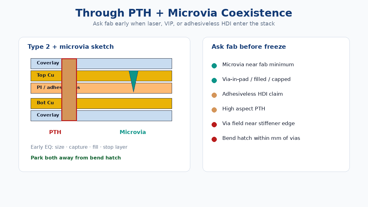
Coexistence is normal on dense double-sided or build-up flex: mechanical PTH for power/ground or connector lands, laser blind/microvia for escape. It is also where quotes diverge.
| Via mix | Early fab questions | If you skip them |
|---|---|---|
| PTH only | Hole size, aspect, plate class, keep-out from bend | Over/under plate; vias in hinge |
| PTH + laser microvia | Capture pad, residual Cu, laser stop layer, fill/cap | Capability EQ after artwork freeze |
| Via-in-pad / filled | Fill material, planarization, finish compatibility | Solder void / coplanarity scrap |
| High aspect PTH | Max aspect Plant A vs B; back-drill N/A on flex | Thin barrels or refusal |
| Dense via fields near stiffener | Keep-out from stiffener edge / coverlay step | Crack at thickness step |
Ask early when any of these are true: microvia diameter near fab minimum, via-in-pad, adhesiveless HDI claim, controlled impedance on flex, IPC Class 3 flex, or bend hatch within a few millimeters of a via field. Send a draft stack + via legend (PTH vs blind, sizes, plate intent) before copper freeze — cheaper than respinning after CAM says “we don’t laser that construction.”
Stiffener, coverlay, and finish — buyer notes that protect vias
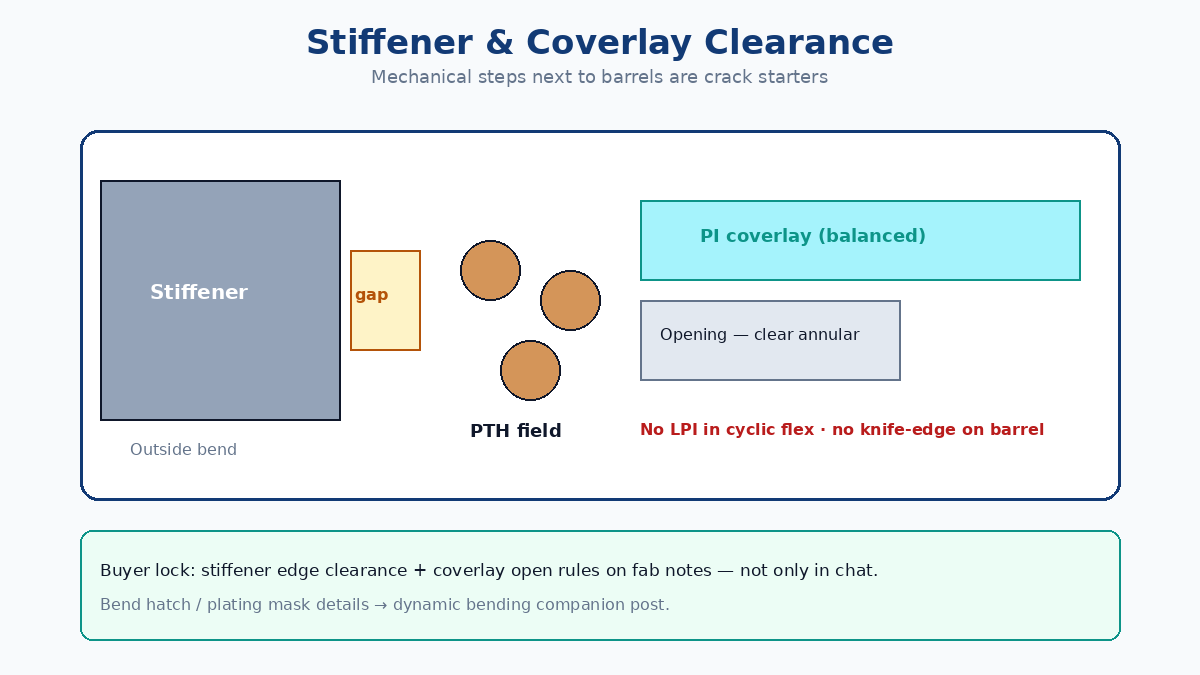
Vias fail not only from plate thickness but from mechanical steps next to barrels: stiffener edges, coverlay openings, and finish build.
| Feature | Buyer lock | Via-related fail mode |
|---|---|---|
| Stiffener (PI / FR4 / steel) | Outside bend; clearance from via fields & coverlay steps | Edge acts as crack starter into pad/barrel |
| Coverlay vs LPI | PI coverlay on flex; LPI only where fab agrees (often stiff zones) | LPI crack → Cu expose; coverlay step at via ring |
| Coverlay opening | Clearance to pad / annular; no knife-edge on barrel | Tear / stress riser at open edge |
| Surface finish | ENIG / OSP / immersion Ag per solder & flex life | Thick finish + via-in-pad = coplanarity / wet issues |
| Selective finish | Finish only pads that need solder | Extra metal in flex window stiffens |
| Shield / EMI film | Window around vias and bend per dynamic rules | Continuous shield over via field + hinge |
Bend-zone geometry, plating mask, and cycle acceptance belong in double-sided flex dynamic bending — use that post for no-via hatch, single-Cu windows, and ΔR flex test language. This article’s job is via plating, materials, and RFQ fields that keep barrels reliable where vias are allowed.
China fab RFQ matrix: vias out of trouble
Paste into the quote package so every bidder prices the same via risk (and so Plant A’s “standard plate” matches Plant B):
| RFQ field | What to specify | Fail mode if missing |
|---|---|---|
| Construction | Double-sided FPC / IPC-6013 Type 2 (or stated) | Quoted as rigid-ish or wrong type |
| Product vs blog paths | Capability: product page; design rules: this + dynamic post | Slug collision / wrong page cited |
| Laminate | Adhesive vs adhesiveless; stack T; Cu RA/ED + weight | Wrong HDI/cost path |
| PTH plate | Target class ~10–12 µm (confirm); min barrel if needed | Under/over plate surprise |
| Bend / thin zones | Max finished Cu; plating mask / selective plate | Hinge over-plated |
| Via legend | PTH sizes; blind/microvia sizes; VIP yes/no | Laser EQ after freeze |
| Keep-outs | No via/pad/stiffener in bend hatch (link dynamic post) | Vias in cyclic zone |
| Coverlay / stiffener | PI coverlay; stiffener material & edge clearance | Step cracks into vias |
| Finish | ENIG/OSP/…; selective if needed | Finish in flex window |
| Acceptance | Continuity, thermal stress / microsection if Class requires | Visual-only escape |
| Bend life | Point to dynamic-bending RFQ block when cyclic | Static quote for dynamic part |
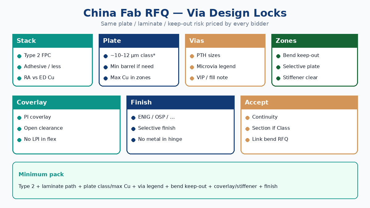
Minimum viable pack: Type 2 callout + adhesive/adhesiveless + plate class / max Cu in zones + via legend (PTH ± microvia) + bend keep-out reference + coverlay/stiffener clearance + finish. Add Class / coupon language only when the program needs it.
Soft close for XFPCB buyers
If vias are cracking, intermittent, or blocking HDI escape on a double-sided flex, send the stack table (adhesive vs adhesiveless), via legend with plate intent, bend hatch reference, and stiffener/coverlay notes with the Gerbers — not only “2-layer flex PTH, best price.” XFPCB can sanity-check plating windows against flex areas, microvia feasibility, and traveler keep-outs so production does not treat every hole like a rigid panel plate-through.
Start from the double-sided flex product page for capability framing, use dynamic bending for hinge rules, then attach the RFQ matrix on this page so every China fab answers the same via-design questions.