
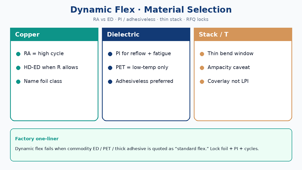
Dynamic flex material selection starts with copper ductility and stack thickness, not with a generic “polyimide flex” checkbox. Rolled annealed (RA) copper usually wins for high cycle life; electrodeposited (ED) copper can be enough for install bends and lower cycle targets when you pick a high-ductility grade and keep the stack thin. Polyimide (PI) film — preferably adhesiveless for dynamic hinges — outlasts PET under heat and fatigue; adhesive and coverlay must stay thin enough to leave radius budget without starving bond strength. Buyers who lock copper type, PI thickness, adhesiveless yes/no, bend cycles/radius, and current-capacity caveats into the China RFQ stop quoting “standard flex” that fails in the field.
This China-fab guide answers first: RA vs ED for bend life vs cost, when high-ductility ED is enough, thinner bend windows with ampacity tradeoffs, PI vs PET and adhesiveless preference, adhesive/coverlay thin-but-not-too-thin, and the RFQ matrix that locks bend-life intent. Geometry keep-outs and via fatigue live in companion posts — materials here, bend-zone artwork there.
Answer first: RA vs ED for bend life vs cost
| Term | Factory meaning | Why buyers care |
|---|---|---|
| Dynamic flex | Repeated bend to a radius/angle for a cycle-life target | Fatigue scrap, intermittent opens, field returns |
| RA copper | Rolled annealed foil — elongated grains, high ductility | Default for high-cycle hinges |
| ED copper | Electrodeposited foil — often cheaper, lower ductility unless HD grade | Cost / lead-time play; risk if “ED” alone is written |
| High-ductility ED (HD-ED) | ED process tuned for elongation closer to RA | Static/install or mid-cycle where RA MOQ hurts |
| Adhesiveless PI | Cu bonded to PI without acrylic adhesive core | Thinner stack, better registration, preferred for dynamic |
| Coverlay | PI film + adhesive over conductors (not LPI in cyclic bend) | Protects Cu; thickness moves neutral axis and radius |
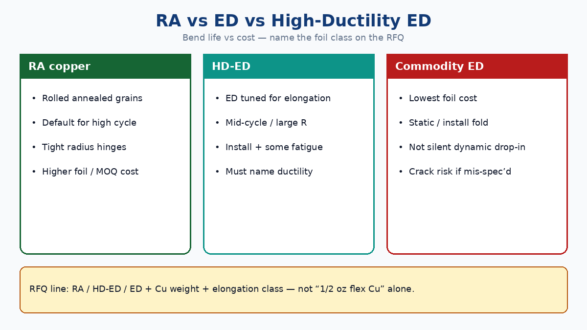
Answer-first rule: specify RA copper for dynamic bend layers when cycle life and tight radius matter. Spec ED or HD-ED only when you can prove the cycle class and radius allow it — and name the ductility class on the RFQ so Plant A does not substitute commodity ED against Plant B’s RA quote.
| Copper choice | Bend-life intent | Cost / MOQ reality | Fail mode if mis-spec’d |
|---|---|---|---|
| RA (typical dynamic default) | High cycle, tight R, Type 2 hinge | Higher foil cost; sometimes longer lead | Avoided for price → early Cu crack |
| Commodity ED | Static fold / install bend | Lowest foil cost | “ED flex” sold as dynamic |
| High-ductility ED | Mid-cycle or large R; RA unavailable | Between RA and commodity ED | Written as “ED” with no elongation callout |
| RA + electrolytic plate thicken | Via plate needed outside bend | Plate adds brittle Cu | Plate left on in bend → fatigue |
Related bend-zone geometry (vias out of the hinge, plating mask): double-sided flex dynamic bending. Via/plating tradeoffs: double-sided flex via design.
💡 Procurement Pro-Tip: Ask for foil type + elongation class (or RA / HD-ED / ED) on the same line as copper weight. A quote that only says “1/2 oz flex Cu” is not comparable across China fabs.
When high-ductility ED is enough
Not every flex is a million-cycle scanner hinge. High-ductility ED earns a place when:
| Use case | Why HD-ED can work | Still lock on RFQ |
|---|---|---|
| One-time / few-cycle install bend | Strain is mostly forming, not fatigue | Radius, angle, “static/install” label |
| Large bend radius vs stack T | Peak strain stays low | R and T both stated |
| Mid-cycle targets (e.g. low thousands) with generous R | Elongation margin may suffice | Cycle target + ΔR acceptance |
| RA MOQ / lead time blocks NPI | HD-ED bridges pilot builds | Confirm foil datasheet elongation; re-qualify for volume |
| Single-sided or single-Cu window | Thinner stack reduces demand on foil | Construction type + Cu window note |
Do not treat HD-ED as a silent drop-in for RA on a high-cycle, small-radius double-sided hinge. If the fab says “we use special ED for flex,” demand the ductility/elongation callout and a sample flex-test plan. Commodity ED that looked fine at first fold often cracks after NPI burn-in cycles.
Thinner bend window — with current-capacity caveats
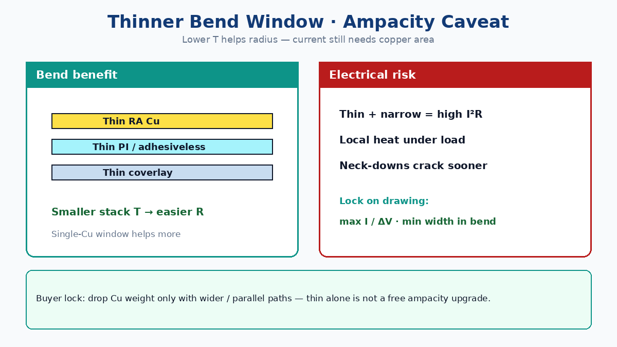
Thinner copper and thinner dielectric shrink stack thickness T, which improves bend radius at a given multiplier — but ampacity and voltage drop do not shrink with marketing slogans.
| Lever | Bend benefit | Electrical caveat |
|---|---|---|
| 1/2 oz / 12–18 µm Cu (often RA) | Lower stiffness; better fatigue at given R | Higher I²R; wider traces or parallel paths needed |
| Single-Cu bend window | Removes opposite-layer stiffness | Return / ground may need alternate path outside window |
| Thinner PI core (e.g. 12.5–25 µm class) | Smaller T → easier R | Tear / handle risk; fab capability varies |
| Adhesiveless vs thick acrylic | Removes adhesive thickness from T | Different etch / adhesion process — quote as such |
| Narrow high-cycle traces | Less Cu volume in hinge | Local heating; neck-downs are crack starters under load |
Buyer practice that sticks: put min trace width in bend, max current per net (or max ΔV), and Cu weight on the same fab note. “Make it as thin as possible” without ampacity is how NPI passes flex life and fails thermal or IR drop at system test.
Rule-of-thumb geometry still belongs with the fab and IPC-2223 guidance for your layer count and cycle class — materials only buy you the right T and ductility; they do not replace bend keep-outs and plating mask.
⚠️ Factory callout: If you drop Cu weight for bend life, widen traces or add parallel fingers in the window before CAM. Thin + narrow + high current is a burn-and-crack stack.
PI vs PET; adhesiveless preference for dynamic
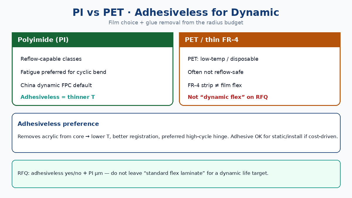
| Substrate | Heat / solder | Fatigue / dynamic | Typical buyer use |
|---|---|---|---|
| Polyimide (PI) | Reflow-capable classes; high Tg film | Preferred for cyclic bend | Dynamic FPC, most China flex builds |
| PET | Lower heat; often not reflow-safe | Limited dynamic; cheap static | Disposable / low-temp interconnects |
| Thin FR-4 / “FR-4 flex” | Glass-epoxy; not film flex | Install bend only — not dynamic PI | Mis-quoted as flexible PCB |
PI vs broader flex framing: polyimide PCB advantages and disadvantages and advantages of flexible PCBs.
Adhesiveless preference for dynamic: adhesiveless PI-Cu laminates remove the acrylic adhesive layer from the core, which:
- Reduces stack thickness T for a given Cu/PI pair
- Improves dimensional stability and registration for fine pitch / HDI
- Avoids adhesive creep and glass-transition soft spots in the cyclic zone
Adhesive (acrylic) stacks remain common and cheaper for static or install-bend Type 2 with looser pitch. For high-cycle dynamic hinges, write adhesiveless = yes (or “adhesiveless preferred; adhesive only if fab proves R and cycles”) so quotes do not silently add 25–50 µm of glue into your radius budget.
| Stack choice | Prefer when | Avoid when |
|---|---|---|
| Adhesiveless PI + RA Cu | Dynamic, tight R, HDI/microvia | Absolute lowest unit cost on static cable |
| Adhesive PI + RA Cu | Static/install; cost-sensitive | High cycle + small R without proving T |
| PET + ED | Low-temp disposable | Soldering + dynamic + “looks like FPC” |
| Thin FR-4 strip | One-time form | Called “dynamic flex” on RFQ |
Adhesive / coverlay: thin — but not too thin
Coverlay and any remaining adhesive are not “thinner is always better.” They must protect copper and hold the stack through etch, plate, and flex — while leaving enough radius budget.
| Layer | Thin-enough practice | Too thin / too thick failure |
|---|---|---|
| Coverlay PI film | Common flex classes (e.g. 12.5–25 µm film) matched to fab capability | Too thick → stiff hinge; too thin → puncture / poor dielectric |
| Coverlay adhesive | Thin flex-rated systems; balanced openings | Thick glue eats T; starved glue → delam at coverlay edge |
| Core adhesive (if not adhesiveless) | Minimize in bend region; prefer adhesiveless for dynamic | Acrylic soft under heat + cyclic strain |
| LPI solder mask | Forbidden in cyclic bend | Mask cracks → Cu exposed → fatigue |
| Edge / opening geometry | Keep abrupt coverlay steps out of peak strain line | Crack at coverlay window edge |
Thin-but-not-too-thin buyer language: “Dynamic bend: PI coverlay (no LPI); adhesiveless core preferred; coverlay adhesive as thin as fab process allows without delam risk; openings balanced for neutral axis.” Attach a one-line stack sketch (Cu / PI / coverlay thicknesses) — one sketch prevents three EQ loops.
Coverlay balance and plating interaction with vias: see via design and dynamic bending.
China fab RFQ matrix: lock bend-life intent
Paste into the quote package so every bidder prices the same materials risk:
| RFQ field | What to specify | Fail mode if missing |
|---|---|---|
| Copper type | RA / HD-ED / ED + weight (e.g. 1/2 oz RA) | Commodity ED on a dynamic quote |
| PI thickness | Core film µm (and whether adhesiveless) | Thick adhesive stack silent on quote |
| Adhesiveless | Yes / no / preferred with fallback | Cheap adhesive Type 2 for high cycle |
| Coverlay | PI coverlay; adhesive class; no LPI in bend | LPI or thick coverlay in hinge |
| Bend cycles / radius | Cycle target + R + stack T intent | Static radius used for dynamic part |
| Bend class | Dynamic vs static/install | “Flex” treated as one-time fold |
| Current / trace | Max I or ΔV; min width in bend | Thin Cu burns or IR-fails |
| Geometry link | Bend-zone keep-out; plating mask if Type 2 | Vias/plate in window (see companions) |
| Acceptance | Flex test + ΔR / open criteria | Scrap found only at system test |
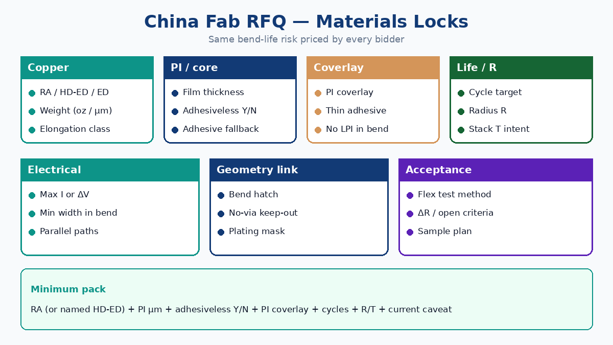
Minimum viable materials pack: RA (or named HD-ED) + PI thickness + adhesiveless yes/no + PI coverlay (no LPI) + cycle target + radius (with T) + current caveat for thin Cu. Then point the fab at bend-zone hatch and plating-mask notes in dynamic bending and via design.
IPC references buyers may cite (confirm edition with fab): IPC-2223 (flex design), IPC-6013 (flex performance types), foil/elongation language per laminate datasheet — materials callouts without bend geometry are incomplete; geometry without foil type is incomplete too.
Soft close for XFPCB buyers
If copper cracks, delamination at coverlay edges, or early ΔR rise already showed up on a “standard flex” build, send copper type intent (RA vs ED), PI / adhesiveless preference, coverlay stack sketch, bend cycles/radius, and current limits with the Gerbers — not only “flex PCB, best price.” XFPCB can review RA vs HD-ED feasibility, adhesiveless stack options, thin coverlay process windows, and align materials with bend-zone keep-outs so production does not quote a static PET or commodity-ED stack against a dynamic life target.
Start from the related primers linked above, then attach the RFQ matrix on this page so every China fab answers the same material and bend-life questions.