
Industrial control boards that “wire a 12V latching relay like a hobby breadboard” usually fail in the same places: coil pulse polarity and duration never make it into the assembly drawing, flyback energy lands on the wrong net, copper under the coil is undersized for pulse current, and the switched load shares copper or creepage with logic grounds that were never meant to see that energy. This page is a factory/buyer latching (bistable) 12V relay wiring guide for PCB and PCBA — set/reset coil vs single-coil pulse, polarity, flyback/TVS, copper and footprint choices, load-vs-logic isolation, and DFM/RFQ notes for China fab plus assembly of industrial control boards. Soft CTA only. No competitor brands. No invented XFPCB electrical capability claims.
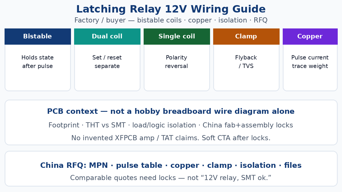
What “latching” means on an industrial control PCB
A latching relay (bistable relay) holds its last contact state after the coil drive is removed. A short set pulse closes (or opens) the contacts; a reset pulse returns them. Holding current is not required the way it is on a conventional monostable relay.
For battery-backed panels, remote I/O, and industrial microcontroller boards that sleep between events, that property cuts continuous coil heating and standby current. For PCB buyers it also changes what must appear on the schematic and fab notes: pulse polarity, pulse width window, which coil pins are set vs reset, and what must never be left floating on the driver.
Two coil architectures dominate 12V latching parts:
| Topic | Dual-coil (set / reset) | Single-coil (polarity reversal) |
|---|---|---|
| Coil pins | Separate set and reset windings | One winding; direction sets state |
| Drive | One-shot pulse into the active coil | Forward pulse = set; reverse = reset |
| Driver | Two low-side switches or drivers | H-bridge or polarity-reversing stage |
| Common PCB risk | Wrong coil pinout / both coils pulsed | Polarity swap in CAD or harness |
| Hold power | Near zero after pulse | Near zero after pulse |
Neither architecture is “more industrial” by itself. Dual-coil is often easier to drive from discrete transistors on a control board. Single-coil saves a winding and a pin budget but forces careful polarity management in layout and firmware.
Dual-coil set/reset on the board
Treat set and reset as two independent pulse channels that must never stay asserted.
Buyer locks that belong on the schematic and assembly notes:
- Coil voltage — 12 V nominal; confirm pick-up and drop-out windows against the rail under load, not only against a lab bench supply
- Pulse width — datasheet min/max; too short fails to toggle; too long overheats a coil that was never rated for continuous duty
- Coil resistance / pulse current — size drivers and copper for the pulse, not for a mythical continuous hold current of zero
- Pin map — set vs reset labeled on the silk and on the BOM notes so SMT/THT operators do not mirror a dual-coil footprint from memory
Firmware and discrete logic should enforce mutual exclusion: set and reset pulses do not overlap. On a dual-coil part, simultaneous drive can fight the magnetic structure and waste current into heat.
If the board uses an industrial microcontroller for sequencing, put the pulse timing and interlock rules in the software design note that travels with the RFQ — not only in a firmware repo the fab never sees. Prose about industrial microcontroller boards stays design context here; do not treat sibling blog URLs as nav.
Single-coil polarity reversal
A single-coil latching relay sets or resets by reversing coil current. On the PCB that usually means an H-bridge, a dual MOSFET pair, or a dedicated relay-driver IC that can reverse the coil rails for a timed pulse.
Layout and BOM traps:
- Polarity in CAD — a mirrored footprint or swapped net names silently invert set and reset relative to firmware
- Pulse symmetry — set and reset pulse widths may not be identical in the datasheet; copy both numbers into the driver note
- Freewheel path — reversing drive changes where inductive energy returns; a diode pattern that worked for a single low-side monostable coil is often wrong for an H-bridge
Do not assume “any 12V latching relay” accepts the same H-bridge timing. Lock the MPN, the recommended pulse table, and the driver topology on the quote packet.
Flyback, TVS, and where energy goes
Every coil is an inductor. When the pulse ends, stored energy must return somewhere that does not destroy the driver or couple into logic.
Practical PCB choices for 12V latching coils:
- Flyback diode across a unidirectional coil drive (classic dual-coil low-side switch) — polarity must match the intended coil current direction
- Bidirectional TVS or RC snubber across the coil when the driver reverses polarity and a single diode would short one drive phase
- TVS or clamp on the switched load contacts when the load is inductive (solenoid, contactor coil, motor) — contact welding and EMI often start on the load side, not the coil side
- Placement — clamps sit close to the coil or contact pins with short loops; long traces turn the clamp into decoration
Call the clamp parts on the BOM with clear “do not DNP” language when the design depends on them for driver survival. Unpopulated flyback pads are a common first-article killer on “cost-down” assembly quotes.
Copper, trace, and via for coil pulse current
Latching coils draw little average current but can draw amps for milliseconds. Trace width, copper weight, and via count must survive that pulse and the thermal environment of an industrial enclosure.
When coil or switched-load current pushes past ordinary signal copper, route the conversation through Heavy Copper PCB language: ounce weight on the coil and power layers, external vs internal copper, and whether pours or discrete traces carry the pulse. Do not invent a shop’s maximum ounce rating in marketing copy — state the copper weight you need on the stack-up note and ask bidders to acknowledge it.
Buyer checks:
- Trace width calculator results for pulse current and temperature rise, filed with the RFQ
- Via count under coil pins and under high-current contact landings
- Separation between coil copper and sensitive analog or MCU nets that share the same plane edge
- Connector and fuse copper sized for the switched load, not only for the coil
A 12V latching coil on 1 oz copper with a single skinny trace may “work” on the bench and still brown out a shared rail or heat a via barrel in the field.
Footprint: THT vs SMT latching relays
Latching relays still ship in both through-hole and SMT packages. Choice is mechanical and process, not fashion.
Through-hole — better for high vibration, high contact current, field-replaceable sockets, and hand rework on industrial panels. Needs correct hole size, annular ring, and wave or selective-solder process notes. Pin 1 / set-coil orientation must be unmistakable on silk.
SMT — denser panels, reflow with the rest of the board, but watch package mass, pad peel, and tombstone risk on small signal relays. Stencil aperture and pad geometry follow the relay datasheet, not a generic “relay” library.
Either path is ordinary PCB Assembly work when the traveler names process (SMT reflow, wave, selective, hand), orientation marks, and any press-fit or socket secondary ops. Mixed THT relay + SMT MCU on one industrial board is common; say so in the assembly notes so quotes do not assume pure SMT.
Keep socketed vs soldered decisions explicit. A socket changes the PCB footprint and the service model; it is not a silent BOM swap.
Isolating the switched load from logic
Latching relays exist to keep a load circuit away from fragile logic — until layout reunites them on a shared pour.
Isolation discipline that belongs in DFM:
- Creepage and clearance between contact nets and MCU/ADC nets for the declared working voltage and pollution degree
- Separate return paths — load return and logic ground meet at one intentional star or filter, not under the relay body by accident
- Slotting / keep-outs when the safety or EMC file requires them; document slots on the mechanical layer so CAM does not “optimize” them away
- Contact rating vs load type — resistive vs inductive vs lamp inrush; derate and snub the load side
Industrial control panels often mix 12V coil logic with higher-voltage switched circuits on the same rigid board. A coherent Multilayer PCB Guide stack-up (dedicated power/ground, controlled spacing, clear layer assignment for coil vs load) beats hoping a two-layer hobby layout scales into a cabinet.
Prose about industrial PCB manufacturing stays context for buyers evaluating fab discipline; do not href sibling articles as if they were nav.
DFM and RFQ locks for China fab + assembly
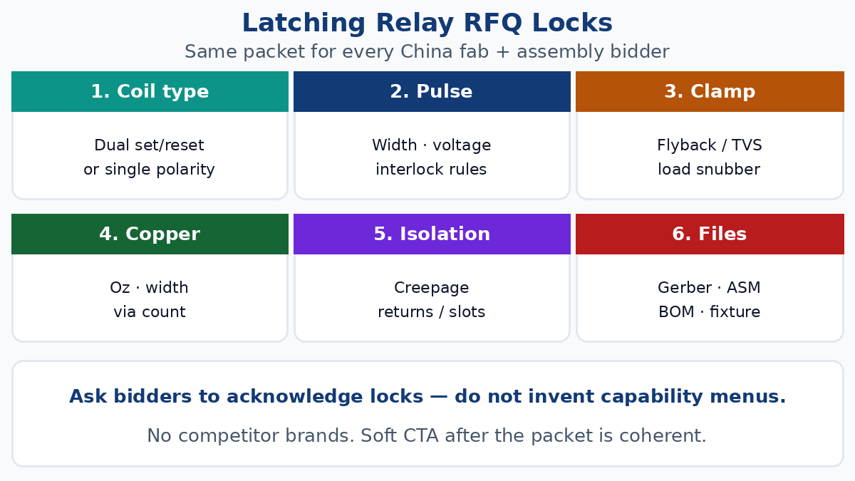
Comparable quotes need locks, not “relay board, 12V, SMT ok.”
Put this packet in front of every bidder:
- Relay MPN(s) — coil type (dual vs single), coil voltage, contact form (SPST/SPDT/DPDT), contact rating, pulse table
- Footprint source — datasheet land pattern or hole table; THT vs SMT called out
- Driver topology — discrete, H-bridge, or IC; clamp parts populated
- Copper weight — especially coil and load paths
- Isolation / creepage notes — working voltages and any slotting
- Assembly process — reflow, wave, selective, hand; orientation and pin-1 marks
- Test intent — continuity on coil pins, set/reset functional pulse on a bed-of-nails or fixture if required, contact load test scope
Ship that intent through coherent Manufacturing Files: Gerbers or ODB++, stack-up, fab drawing, assembly drawing, BOM with MPN and DNP rules, centroid, and any fixture notes. Vague “relay wiring like the blog diagram” is not a fabrication input.
When a bidder’s technical questions need a capability conversation (layer count, copper, finish, holes), point them at published Technical Capabilities and require written acknowledgment against your locks — do not paste invented pitch, TAT, or ampere claims into the RFQ as if they were catalog lines.
Quick-turn prototype spins of industrial control boards still need the same pulse, clamp, and isolation locks; schedule pressure is not a reason to omit flyback parts or copper notes.
Common failure modes buyers actually see
- Relay never toggles — pulse too short, rail sag under pulse, wrong coil pin, firmware polarity inverted vs silk
- Toggles once then sticks — contacts welded from unsnubbed inductive load; coil overheated by continuous drive mistaken for “hold”
- MCU resets when relay fires — shared return, missing clamp, long coil loop radiating into reset nets
- First-article polarity chaos — dual-coil footprint mirrored; single-coil H-bridge nets swapped in ECAD
- Quote mismatch — one bidder prices pure SMT; another assumes hand-solder THT; neither priced the fixture pulse test you expected
Write the failure mode you care about into the acceptance note. “Board powers on” is not a latching-relay acceptance test.
Soft close for buyers
If the schematic, copper, clamp, isolation, and file packet already agree, the remaining work is ordinary fab and assembly execution against those locks. When you are ready to request a comparable China fab+assembly quote for an industrial control board with 12V latching relays, use the site order path with the locks above attached — soft ask only, no invented capability menu. Keep How to Place an Order and quick-turn options as process steps in your internal checklist; the packet quality still decides whether quotes are comparable.