
Boards that ship Wi-Fi, Bluetooth, GNSS, and a sub-GHz link such as LoRa on one PCB fail in the field for a boring reason: one radio’s TX lands in another radio’s RX while both must work at once. Lab benches that test radios one at a time hide the problem. China fab and PCBA quotes that only list layer count and “RF controlled impedance” hide it too. This note is the RFQ / DFM gate for multi-radio coexistence — the aggressor → coupling path → victim frame, desense and blocking, same-band Wi-Fi/BT with packet traffic arbitration (PTA), harmonics and out-of-band energy, antenna placement with S21 isolation language, GNSS as the most fragile victim, RF filtering without brand recipes, PDN and TX current bursts, zoning with shield cans and ground via fences, a short controlled-impedance callout for RF feeds, manufacturing tolerances that move match, and the concurrent TX/RX test matrix a traveler must quote. It is not an antenna feed-matching deep dive, not a 5G materials brochure, and not a price or capability claim sheet.
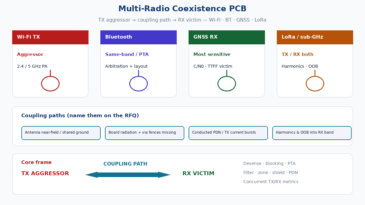
Aggressor, path, victim — name the failure before CAM
Coexistence is not “EMI in general.” Write three named roles on the RFQ and in layout reviews:
| Role | What it is | Typical on this class of board |
|---|---|---|
| TX aggressor | Radio transmitting at full or burst power while another receives | Wi-Fi 2.4/5 GHz PA, LoRa/sub-GHz TX, BT advertising bursts |
| Coupling path | How energy reaches the victim | Antenna near-field / shared ground, board radiation, conducted via PDN or shared shield, harmonic / OOB into RX band |
| RX victim | Radio trying to hear a weak wanted signal | GNSS L1 (and multi-band GNSS), BT LE RX, Wi-Fi RX under concurrent LoRa TX, LoRa RX under Wi-Fi TX |
Desense is sensitivity loss on the victim while the aggressor transmits. Blocking is a strong out-of-band tone that compresses the victim front end so the wanted signal disappears even when the aggressor is not on the victim’s channel. Same-band Wi-Fi and Bluetooth share spectrum and time; they need coexistence arbitration (PTA or equivalent) in the chipset/firmware plan, not only copper distance. Harmonics and OOB from a LoRa PA or Wi-Fi PA can land on GNSS or another RX even when fundamental bands look “far apart” on a napkin sketch.
If the RFQ never names which radio may TX while which must RX, the PCBA house will quote AOI and a single-radio smoke test — and you will discover desense after tooling.
Same-band Wi-Fi / BT and PTA — copper cannot replace time sharing
2.4 GHz Wi-Fi and Bluetooth sit in the same ISM band. Layout isolation helps; it does not replace packet traffic arbitration. On combo modules or discrete Wi-Fi + BT SoCs:
- Put PTA / coexistence pins and firmware policy on the NPI checklist: who wins when both want airtime, how long TX is blanked, and whether LE advertising is allowed during Wi-Fi bursts.
- Treat shared antennas and diplexers as RF architecture decisions, not CAM Afterthoughts — keep-outs and feed lengths still matter when PTA is correct.
- Do not assume “module with built-in coexistence” means your board antennas and PDN are safe. Module vendors assume their reference keep-outs; your LoRa PA and GNSS LNA still live on your copper.
Buyers who only ask for “Wi-Fi + BT module, 4-layer” without coexistence intent get boards that pass single-radio PER and fail when both stacks run under load.
Antenna placement and S21 isolation language
Antennas are the loudest coupling path on a compact IoT board. Factory-useful language:
- State antenna keep-outs (no copper, no ground pour, no metal can, no battery under the element) per radio — Wi-Fi/BT, GNSS, LoRa — as mechanical and fab notes, not only a CAD layer someone deletes in CAM.
- Ask for S21 isolation (or equivalent port-to-port isolation) between antenna feeds or connectors when the OEM has a number. Isolation in dB is the buyer language; do not invent a target — confirm with the RF owner.
- Separate polarizations, edges, and board corners where possible; stacked chip antennas with shared ground necks are a common desense geometry.
- Route RF feeds away from digital clocks, DC-DC switch nodes, and LCD FPC tails. A short controlled-impedance callout belongs on the RF feed (see below); matching network topology belongs in your antenna-feed work, not duplicated here.
GNSS patch or chip antennas parked next to a 2.4 GHz Wi-Fi antenna with a shared ground pour and no fence will show C/N0 collapse the first time Wi-Fi TX hits full rate — even when each antenna “works” alone on a chamber plot.
GNSS as the most sensitive victim
GNSS receivers hear signals tens of dB below thermal noise floors that Wi-Fi and LoRa ignore. Treat GNSS as the default RX victim in every coexistence review:
- L1 (and L5/E5 when used) sits near harmonics and OOB skirts from cellular, Wi-Fi, and some sub-GHz PAs depending on architecture.
- Front-end SAWs/BAWs and LNAs are easily compressed by nearby TX. Blocking looks like “no fix” or long TTFF under Wi-Fi load.
- Active antennas and external LNA bias need quiet PDN; switching noise on the bias rail is conducted desense.
- Metrics that matter on the traveler: C/N0 per constellation, TTFF cold/warm/hot under aggressor TX, and whether a fix holds while Wi-Fi throughput or LoRa TX cycles run.
A board that reports “GNSS OK in open sky, radios off” has not passed coexistence.
RF filtering — types without brand recipes
Filtering is how you break coupling paths that antennas and distance cannot. Speak in filter function, not catalog part recipes:
- Low-pass after a PA to cut harmonics that land on GNSS or another RX.
- Band-pass to pass the wanted band and attenuate neighbors.
- Notch when a known aggressor tone sits near a victim band.
- SAW / BAW front-end filters on GNSS and cellular/Wi-Fi paths where the band plan requires steep skirts (confirm package, keep-out, and reflow profile with the fab/PCBA).
- Diplexer / triplexer when one antenna serves multiple bands — placement and ground of the diplexer matter as much as the schematic symbol.
Do not paste a competitor BOM or a branded “recommended network.” State required attenuation intent at the aggressor frequencies, note that filter selection is OEM/RF-owner responsibility, and put footprints, keep-outs, and shield rules on the RFQ so CAM does not “optimize away” the fence around a SAW.
Materials for mmWave or 5G front ends are a separate topic; for Wi-Fi/BT/GNSS/LoRa IoT boards, ordinary RF stack and filter placement usually dominate over exotic laminate brochures — call stack class for RF feeds, then move on.
PDN, TX current bursts, and DC-DC placement
Wi-Fi and LoRa TX draw pulsed current. That burst couples through shared inductors, long ground necks, and switch-node radiation into LNAs and TCXOs:
- Place buck converters and inductors away from GNSS and BT RF islands; treat the switch node as an aggressor the same way you treat a PA.
- Local bulk + high-frequency caps at each radio module; star or carefully partitioned returns so PA return current does not traverse the GNSS ground.
- Separate analog/RF LDO rails from digital when the module vendor requires it.
- Watch shared ferrite beads that look like isolation but saturate under TX bursts and then dump noise.
PDN-induced desense often survives shield cans because the path is conducted. RFQs that only say “add shielding” without PDN notes miss the failure mode.
Zoning, shield cans, and ground via fencing
Physical zoning is the layout half of coexistence:
- Partition the board into RF islands: Wi-Fi/BT, GNSS, LoRa/sub-GHz, digital MCU, and power.
- Shield cans over PA + matching + filter regions when the OEM requires them — footprint, fence vias, and solder process (clip vs SMT can) belong on fab/assembly notes.
- Ground via fences around RF cavities and along sensitive feed edges; spacing and via diameter are confirm-with-fab, not invented µm claims.
- Keep high-speed digital and clock lines out of RF cavities; stitch returns so cans do not float.
- Connector and USB/Ethernet entries should not drag noisy harness returns through the GNSS island.
Shielding without via fences and without PDN discipline is a metal hat over a noisy floor.
Controlled-impedance RF feeds — short fab callout
RF microstrip or coplanar feeds from module to antenna / connector need controlled impedance called out on the stackup and fab notes (typically 50 Ω single-ended unless the module says otherwise). Put impedance class, reference layer, and test coupon intent on the RFQ. Do not rehash a full impedance article here — length matching of feed networks, antenna matching topology, and materials comparisons belong in their own posts. One line that CAM can act on beats three paragraphs of SI theory that never reach the traveler.
Manufacturing tolerances that move RF match
China fab reality moves RF:
- Etch tolerance and copper weight change trace Zo and matching network reactance.
- Solder-mask thickness over microstrip shifts impedance; soldermask-defined vs non-soldermask-defined pads change parasitic C.
- Via stub and finish (ENIG thickness variation) at RF transitions.
- Shield can solder fillet variation and fence via registration.
- Module pin coplanarity and paste volume on RF grounds.
State finish and impedance coupon expectations; confirm process capability with the fab rather than pasting marketing µm numbers into the RFQ.
Concurrent TX/RX test matrix — what the quote must include
Single-radio smoke tests are not coexistence. Require a matrix the PCBA or OEM test house can price:
| Aggressor TX | Victim RX | Metrics to name |
|---|---|---|
| Wi-Fi TX (max MCS / duty) | GNSS | C/N0 drop, TTFF, fix hold |
| Wi-Fi TX | BT LE RX / PER | PER, RSSI/SNR if available |
| BT TX bursts | Wi-Fi RX | Throughput, PER/SNR |
| LoRa / sub-GHz TX | GNSS | C/N0, TTFF |
| LoRa TX | Wi-Fi / BT RX | PER, throughput or RSSI |
| Wi-Fi + BT concurrent (PTA on) | GNSS | C/N0 under combined load |
| All quiet baseline | Each RX | Baseline C/N0, PER, SNR for delta |
Acceptance language should state delta vs baseline (e.g. max allowed C/N0 drop, max PER, min throughput) as OEM-owned numbers — the fab/PCBA quotes the fixture and procedure; they do not invent RF pass criteria. Log aggressor duty cycle, channel, and power so FA can reproduce.
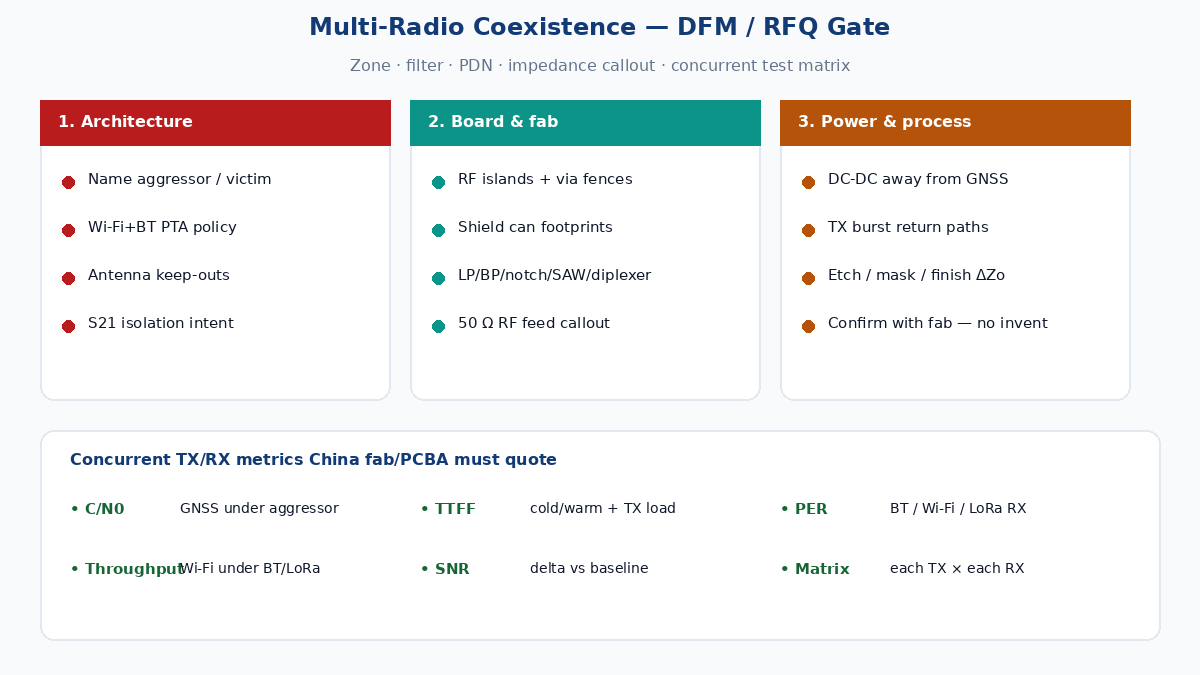
RFQ checklist for China fab + PCBA
Pack this before quote so CAM and test do not strip coexistence:
- Radio list and concurrent use cases (which TX while which RX).
- PTA / coexistence firmware intent for same-band Wi-Fi + BT.
- Antenna keep-outs per radio; mechanical metal and battery keep-outs.
- S21 / port isolation intent if the OEM has a number (confirm, do not invent).
- Stackup + controlled-impedance callout for RF feeds (reference layer, coupon).
- Shield can footprints, fence via intent, and solder process notes.
- RF filter footprints and keep-outs (LP/BP/notch/SAW/BAW/diplexer as used) — function and placement, not brand recipes.
- PDN notes: DC-DC placement relative to RF islands, TX burst current paths, quiet rails for GNSS/LNA.
- RF zoning drawing or notes: islands, via fences, digital keep-out of RF cavities.
- Finish and impedance process notes that affect RF match (confirm with fab).
- Concurrent TX/RX test matrix with metrics: C/N0, TTFF, PER, throughput, SNR — plus baseline vs aggressor deltas and acceptance owned by OEM.
- Fixture access: RF connectors or coupler points, GNSS sky-view or conducted GNSS stim, Wi-Fi/BT/LoRa traffic generators as applicable.
A multi-radio quote that only lists “4-layer, ENIG, impedance control” without aggressor/victim cases and concurrent metrics is a single-radio quote in disguise. Write the gate so the traveler tests what the field will actually do — all radios awake at once.