
Drones and small UAVs pack several different circuit jobs into a light airframe: a flight controller that closes the control loop, ESC power stages that dump amps into motors, GNSS and IMU sensing, radio links for command and telemetry, and often a camera or gimbal board. "PCB for drones" is not one part number. It is a set of boards (or a tightly partitioned stack) that must survive vibration, weight targets, motor EMI, and field temperature — then still pass fab and assembly inspection that matches how the aircraft actually flies.
This guide is for overseas buyers and hardware engineers sourcing China fab / PCBA for commercial, consumer, and industrial drone platforms — inspection, mapping, agriculture, photography, public-safety support — not a deep dive into full aerospace certification programs. It walks board roles, rigid vs rigid-flex choices under shock, ESC copper and thermal stackup, EMI between motors and radios, IPC class and airborne inspection habits, and RFQ fields that make a China quote usable. Confirm copper weight, coat, and vibration notes on your drawing; market "drone boom" blurbs are not stackup specs.
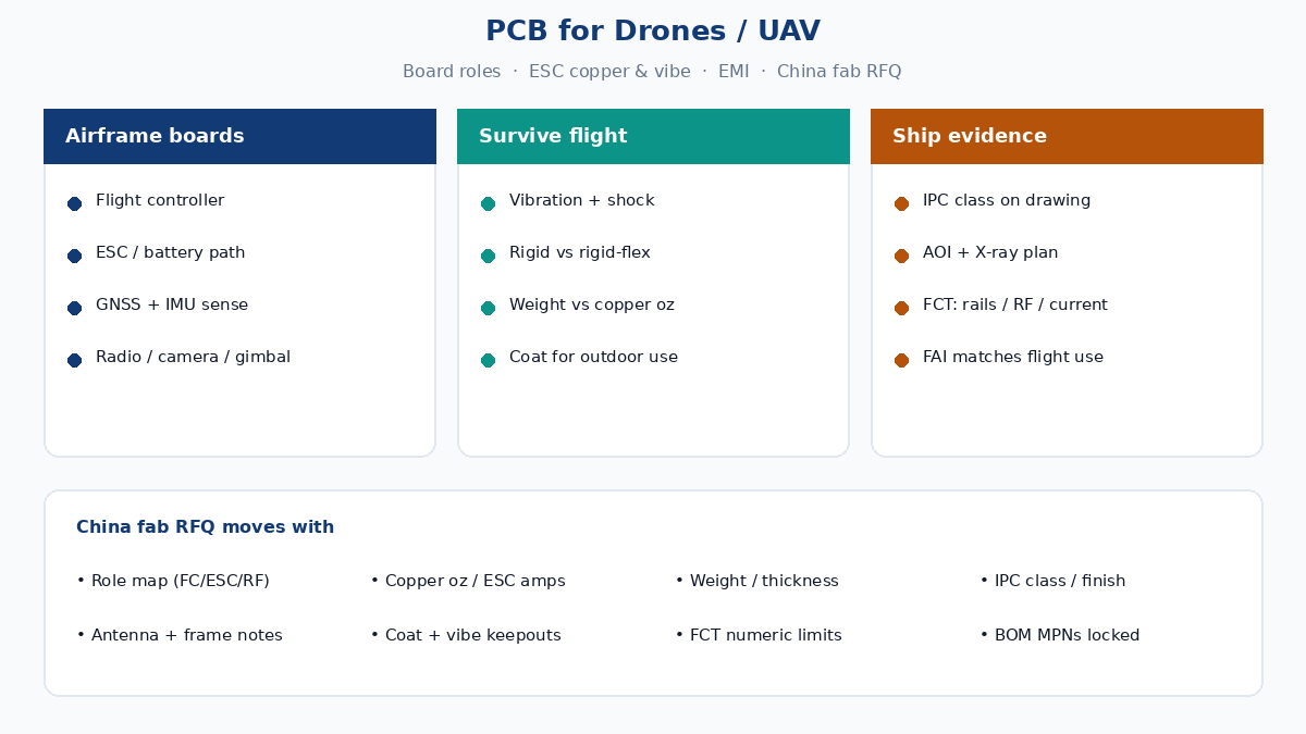
Board roles inside a typical drone stack
Treat the airframe as a small distributed system. Each board (or each zone on a shared carrier) owns a failure mode you can name on the traveler.
Flight controller (FC) — MCU or SoC, IMU interfaces, barometer, magnetometer, PWM / DShot / CAN / UART to ESCs and peripherals, watchdog and failsafe logic. Layout priorities: short, quiet sensor paths; mechanical mounting that does not couple frame torsion into the IMU; clean power for the MCU separate from ESC switching return. Soft-mount foam or rubber is a mechanical feature that still needs keepouts and connector strain relief on the PCB drawing.
ESC / power path — MOSFET or integrated ESC stages, bulk capacitors, current sense, and battery input. This is where copper weight, via farms under power pads, and thermal pours decide whether a hover at full payload cooks the laminate. Multirotor ESCs often sit near motors; lead length, connector plating, and solder joint fatigue under vibration matter as much as MOSFET Rdson.
GNSS / IMU and navigation sensing — GNSS modules want sky view and a clean RF ground; IMUs hate vibration and magnetic distortion from motors and steel fasteners. Buyers who put the magnetometer next to a high-current ESC return path invent "compass dance" that firmware cannot fully fix. Keepout and distance notes belong on the assembly drawing, not only in a pilot checklist.
Radio / telemetry / RC link — 2.4 GHz, 900 MHz, LTE, or proprietary video/control links. Antenna placement fights the carbon frame, battery, and motor wiring. A telemetry board that passes open-air RSSI and then fails inside a carbon fuselage is an enclosure and keepout problem — same class of issue as other RF products, harder because the "enclosure" is also structural and spinning propellers change near-field noise.
Camera / gimbal / companion compute — ISP or SBC boards, flex tails to sensors, brushless gimbal drivers. Rigid-flex often earns its keep here: camera modules move; connectors that survive a desk do not always survive a hard landing. Weight budgets push thinner dielectrics and selective stiffeners rather than a second thick FR-4 carrier everywhere.
Name which boards are in scope on the RFQ. Quoting "drone PCB, 4L FR-4" without FC vs ESC vs camera distinction is how fabs guess copper and coat wrong.
Vibration, shock, and rigid vs rigid-flex
Airborne products see continuous vibration from motors and props, plus shock from landings, transport, and the occasional tip-over. That changes how you choose construction:
- Rigid FR-4 — still the workhorse for FC and ESC carriers when the board is screwed to a stiff plate and connectors are locked. Use adequate board thickness for ESC copper pours; ultra-thin boards that save grams can flex under battery connector load and crack joints.
- Rigid-flex — useful for camera/gimbal folds, folding arms with signal tails, and packing compute into odd volumes without harness mass. Static (form-fit) flex is common; dynamic flex across a hinge needs radius, cycle target, and copper type on the quote — same discipline as other flex jobs, plus propwash and outdoor humidity.
- Connectors and strain — vibration kills poorly supported headers and tall electrolytic cans. Specify adhesive staking, underfill on BGAs where risk warrants it, and connector retainers. Through-hole power connectors on ESC boards often outlast fine-pitch SMT under shock if the drawing calls for them.
Do not copy a desktop IoT stack onto a drone traveler and hope conformal coat alone fixes mechanical life. Coat helps moisture and contamination; it does not replace mounting design or copper that can carry current without overheating.
Shock also shows up in depanel and packing. Tab-route with fixtured break protects fine ceramic capacitors near the outline better than aggressive V-score on a thin ESC board. Ask how panels are broken and how boards are nested in trays when the BOM includes tall MOSFETs and film capacitors.
Weight, stackup, and thermal on high-current ESC boards
Every gram on a multirotor costs flight time. Buyers still cannot starve the ESC of copper and expect cool MOSFETs.
Practical stackup / thermal notes for drone power boards:
- Copper weight — 2 oz outer (or heavier local pours) is common on ESC power paths; signal layers can stay lighter. State oz per layer; "heavy copper somewhere" is not a fab note.
- Via farms and pours — thermal vias under MOSFET and regulator pads, unbroken pours to battery +/−, and enough clearance that motor wiring does not short at the frame.
- Laminate Tg / thermal — continuous hover at high current raises local temperature. Cheap low-Tg material that warps under a heat sink or potting compound is a field fail waiting for summer.
- Bulk capacitance — package size vs vibration; stake or glue tall cans; watch ESL of the path from battery connector to half-bridges.
- Weight vs reliability trade — removing pours to hit a mass target without a thermal simulation or flight-log temperature check is how ESCs desolder themselves mid-mission.
Companion compute and camera boards have the opposite problem: dense fine-pitch parts on thin boards with little copper for heat. Call out which SKU is power-critical vs density-critical so CAM does not apply one copper rule to both.
Battery chemistry and peak current belong in the RFQ power summary. An FCT that only checks "motors spin" without a current or FET temperature window will ship boards that pass the bench and fold under payload.
EMI: motors, ESCs, and radios on the same airframe
Brushless motors and switching ESC stages are broadband noise sources. GNSS, magnetometers, and RF control links sit in the same small volume. Factory English for buyers:
- Return path discipline — ESC high-current return must not share a skinny ground neck with GNSS or FC analog. Star or partitioned returns on the harness and on the PCB plane reduce "random" GPS glitches that look like firmware.
- Filtering and layout — LC or ferrite on sensitive rails; keep switching edges away from antenna feeds; shield cans grounded to plane, not floating.
- Cable routing — motor phase wires are antennas; document recommended routing away from GNSS and video RX in the mechanical package, not only on the schematic.
- Clock and spur awareness — switching regulators on the FC that land on RC or video bands cause packet loss that AOI never sees.
- Carbon and metal frames — structural conductors detune antennas and change ground reference; plan antenna location with the production frame, not a foam bench jig alone.
If the RFQ lists "FC + ESC + GNSS + radio" and includes zero EMI or keepout notes, China CAM will not invent isolation. Attach a simple block diagram with distance targets and antenna keepout DXF where relevant.
Video transmitters and LTE modules add another coexistence layer. Simultaneous high-power video TX and GNSS reception is a layout and filtering problem; say whether simultaneous operation is required so FCT can include a dual-active smoke test instead of sequential "each radio alone" checks that miss real flight conditions.
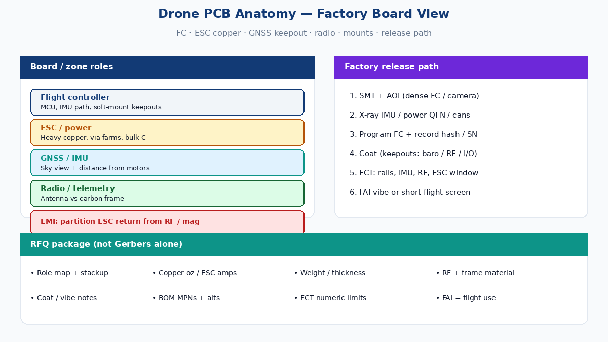
IPC class, inspection, and airborne product habits
Most commercial and industrial drones are not ordered as full aerospace AS9100 programs on day one — and this article is not that certification path. Buyers still need an honest quality class and inspection plan:
- IPC Class 2 is common for prosumer and many commercial builds; Class 3 (or Class 3-like acceptance) appears when downtime or safety-adjacent use justifies the cost. Write the class on the fab note; do not assume the fab upgrades because the product flies.
- AOI catches polarity, bridges, and missing parts on dense FC and camera boards.
- X-ray matters for BGA/LGA IMUs, power QFNs, and hidden joints under shields.
- ICT / flying probe finds opens/shorts; it does not prove a motor can hold current or a GNSS lock outdoors.
- FCT for drones should include rail checks, IMU who-am-I / self-test, radio link or RSSI floor against a golden peer, ESC spin or current window where safe, and firmware hash / serial capture. Numeric limits beat "board boots."
- Conformal coat — common for outdoor and agriculture platforms; define keepouts (connectors, test points, barometer vents, antenna matching). Coat thickness and cure before FCT vs after must be stated so RF and baro behavior match the field unit.
- Vibration / shock notes — even if full DO-160-style testing is out of scope, tell the fab whether you will run a bench vibe screen on FAI and what solder-joint criteria you care about.
Industrial inspection drones that fly near towers or pipelines often add coat, wider temperature, and tougher connector retention than a camera drone for real estate photos. Segment the RFQ the same way you would for industrial vs consumer IoT — different travelers, same China fab.
China fab RFQ fields that change the drone quote
A usable drone PCB / PCBA RFQ is more than Gerbers and "UAV board." Include:
- Board role map — FC, ESC, GNSS/radio, camera/gimbal, or combined carrier; which files belong to which SKU.
- Gerber / ODB++ / IPC-2581, stackup with copper weight per layer, drill, finish, mask, IPC class.
- Weight or thickness targets if they are real constraints — grams or mils, not "as light as possible."
- ESC / power notes — continuous and peak current, MOSFET package, copper oz, thermal via requirements, potting or heatsink interface if any.
- RF / antenna package — module keepouts, cable lengths, frame material (carbon / plastic / metal), coexistence expectations.
- Mechanical / vibe — mounting hole tolerances, soft-mount keepouts, connector staking, rigid-flex bend map if used.
- Environment — outdoor, agriculture chemicals, salt air, operating temperature; conformal coat type and keepouts.
- BOM with MPNs — IMUs, GNSS, MOSFETs, and crystals are not "or equivalent" without review; lock alternates.
- Test specification — AOI/X-ray plan, FCT steps with numeric limits (current, RSSI, sleep if applicable), programming and serial/identity fields, FAI definition including a short flight or bench vibe if you require it.
- Quantity and revision — prototype vs MP, ECO freeze, how many FAI boards before pilot fleet build.
Ask for a traveler outline back: who programs the FC, who runs ESC current check, who coats, and whether RF smoke happens after coat. A quote that only says "SMT + AOI" leaves airborne risk on your desk.
When one PCB serves multiple airframe SKUs (different motor KV, radio region, or camera option), put DNP lists and partial-stuff notes on the assembly drawing. Operators who stuff every footprint will fail weight, current, or RF FCT on the wrong configuration.
Soft next step
When you are ready to source boards for a drone or UAV platform, send the role map, copper/thermal notes for any ESC path, RF keepouts, coat and vibe expectations, and a numeric FCT outline with the Gerbers — then ask the China fab / PCBA partner for a first-article plan that matches how the aircraft actually flies, not only how it looks under AOI. That is how PCB for drones moves from a thin industry headline into hardware that stays in the air.